Descargar la presentación
La descarga está en progreso. Por favor, espere

1
Sujetadores y Tornillos de Potencia
Engineers need to be continually reminded that nearly all engineering failures result from faulty judgments rather than faulty calculations. Eugene S. Ferguson, Engineering and the Mind’s Eye.

2
Perfile roscado Parámetros empleados para definir un perfil roscado
Diámetro mayor, d. Paso por pulgada p=1/n, nº roscas por pulgada Diámetro de cresta, dc Diámetro de paso, dp Diámetro de raiz, dr Text Reference: Figure 15.1, page 667

3
Roscado AVANCE l = tipo roscado x p
(a) Simple, (b) doble, y (c) triple. AVANCE l = tipo roscado x p Text Reference: Figure 15.2, page 667
 Simple, (b) doble, y (c) triple. AVANCE. l = tipo roscado x p. Text Reference: Figure 15.2, page 667.")
4
dc/roscas/pulg/ajuste
Perfiles de rosca ACME UN -- M Uso: potencia, máquina - herramienta UN; 8 series de rosca de paso constante Roscas de paso C-basto F-Fino EF-Extra Fino M; Roscas de paso C-basto F-Fino Ej.MF8X2-G6 ` dc/roscas/pulg/ajuste Ej.UNF1/2X16-1B dc/roscas/pulg/ajuste Text Reference: Figure 15.3, page 668

5
Perfil M y UN Detalle dimensiones de perfiles M y UN.
ht= 0.5p / tan 30º Text Reference: Figure 15.4, page 668

6
Ajuste Equivalencias entre roscas Text Reference: Table 15.1, page 669
Calidad 3(apretado)-9(Suelto) Equivalencias entre roscas Text Reference: Table 15.1, page 669
-9(Suelto) Equivalencias entre roscas. Text Reference: Table 15.1, page 669.")
7
Tornillos de potencia: Perfil ACME
Detalle del perfil - Dimensiones. (valores en pulgadas) Buscamos: mayor ventaja mecánica - posicionamiento. Text Reference: Figure 15.5, page 670
 Buscamos: mayor ventaja mecánica - posicionamiento. Text Reference: Figure 15.5, page 670.")
8
Perfil ACME dp=dc-0.5p-0.01 Text Reference: Table 15.2, page 671
Datos cortante para una longitud de roscado de 1 pulg dp=dc-0.5p-0.01 Text Reference: Table 15.2, page 671

9
Tornillo de potencia con collarín
, Ángulo de avance=ArcTan [l/πdp] Collarín de empuje Text Reference: Figure 15.6, page 672

10
Tornillo de potencia con collarín y husillos de bolas
Text Reference: Figure 15.6, page 672

11
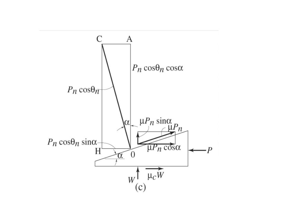
Fuerzas sobre el tornillo de potencia
∑Fv=0 ∑Fh x r =0 DC=OE θn Fuerzas actuando sobre. (a) paralelepípedo ; (b) sección axial; (c) plano tangencial. Text Reference: Figure 15.7, page 673
 paralelepípedo ; (b) sección axial; (c) plano tangencial. Text Reference: Figure 15.7, page 673.")
13
Par torsor el tornillo de potencia
∑Fv=0 ∑Fh x r =0 ASCENSO DESCENSO

14
Ejercicios Determine los pares de torsión, de elevación y de descenso, así coma la eficiencia del tornillo de potencia manufacturado con rosca ACME. ¿es autobloqueante? ¿cual es la contribución de la fricción del collarín, en comparación con la fricción del tornillo, si el collarín tiene, a) deslizamiento, m=0,15 b) rodamiento, m=0,02 ambos en aceite. W=1000lb. Rosca Acme 1,25-5 y Omedio collarín =1,75 in. Mismo ejercicio con W=1000lb. Rosca Acme 1-5 roscado doble y Omc=1,5 in. m=0,16 rosca y 0,12 collarín. Igual que el ejercicio dos, pero con roscado simple.
 deslizamiento, m=0,15 b) rodamiento, m=0,02 ambos en aceite. W=1000lb. Rosca Acme 1,25-5 y Omedio collarín =1,75 in. Mismo ejercicio con W=1000lb. Rosca Acme 1-5 roscado doble y Omc=1,5 in. m=0,16 rosca y 0,12 collarín. Igual que el ejercicio dos, pero con roscado simple.")
15
Tipos de sujetadores roscados
Tornillo y tuerca; (c) Tornillo de cabeza; (c) Birlo. Nota:Arandela o roldana Text Reference: Figure 15.8, page 679
 Tornillo de cabeza; (c) Birlo. Nota:Arandela o roldana. Text Reference: Figure 15.8, page 679.")
16
Equivalencia de la conexión: Sistema de resortes
Bolt-and-nut assembly simulated as bolt-and-joint spring. Text Reference: Figure 15.9, page 680

17
Force vs. Deflection of Bolt and Member
Force versus deflection of bolt and member. (s) Seperated bolt and joint; (b) assembled bolt and joint. Text Reference: Figure 15.10, page 680
 Seperated bolt and joint; (b) assembled bolt and joint. Text Reference: Figure 15.10, page 680.")
18
Fueza vs. Deflexión Text Reference: Figure 15.11, page 681

19
Bolt and Nut Figure Bolt and nut. (a) Assembled; (b) stepped-shaft representation of shank and threaded section. Text Reference: Figure 15.12, page 682

20
Bolt and Nut Assembly Figure Bolt-and-nut assembly with conical fustrum stress representation of joint. Text Reference: Figure 15.13, page 683

21
Gasketed Joint Figure Threaded fastener with unconfined gasket and two other members. Text Reference: Figure 15.17, page 694

22
Constants for Joint Stiffness Formula
Table Constants used in joint stiffness formula [Eq. (15.26)] [From Wileman et al (1991)] Text Reference: Table 15.3, page 684
] [From Wileman et al (1991)] Text Reference: Table 15.3, page 684.")
23
Example 15.6 Figure Hexagonal bolt-and-nut assembly used in Example (a) Assembly and dimensions; (b) dimensions of frustum cone. (All dimensions are in millimeters.) Text Reference: Figure 15.14, page 685
 Assembly and dimensions; (b) dimensions of frustum cone. (All dimensions are in millimeters.) Text Reference: Figure 15.14, page 685.")
24
Strength of Bolts (Inches)
Table 15.4 Strength of steel bolts for various sizes in inches. Text Reference: Table 15.4, page 687

25
Strength of Bolts (Millimeters)
Table 15.5 Strength of steel bolts for various sizes in millimeters. Text Reference: Table 15.5, page 687

26
Coarse and Fine Thread Dimensions
Table Dimensions and tensile stress areas for UN coarse and fine threads. Text Reference: Table 15.6, page 687

27
Coarse and Fine Thread Dimensions - Metric
Table Dimensions and tensile stress areas for metric coarse and fine threads. Text Reference: Table 15.7, page 69

28
Ejercicio – Cilindro hidraúlico
Un cilindro hidráulico de do=150mm y e=2mm sometido a Pi= 250 Kg/cm2 se ha de diseñar con n=1(mínimo). Se embridan las piezas de acero, con una junta elástica. Determinar: tornillo a colocar, calidad, pretensado considerando un 5% de relajación y espesor de juntas. Atornillos=7% At,junta Roscas finas MF Métrica Área esfuerzo, mm2 Material disponible: calidades 10 61.2 5.8,8.8, 9.8 y 10.9 12 92.1 e juntas=0,25mm 16 167 20 272 E2/E1=1400
. Se embridan las piezas de acero, con una junta elástica. Determinar: tornillo a colocar, calidad, pretensado considerando un 5% de relajación y espesor de juntas. Atornillos=7% At,junta. Roscas finas MF. Métrica. Área esfuerzo, mm2. Material disponible: calidades ,8.8, 9.8 y e juntas=0,25mm E2/E1=1400.")
29
Separation of Joint Figure 15.15 Separation of joint.
Text Reference: Figure 15.15, page 690

30
Cyclic Load Figure Forces versus deflection of bolt and joint as function of time. Text Reference: Figure 15.16, page 691

31
Factor Concentración Fatiga
Ka,e Factor de concentración de esfuerzos, incluye el factor acabado superficial Se=Se´KaKbKcKdKeKg=Se´Ka,eKbKcKdKg=Se´Ka,eKdKg Kb,axial=1 Text Reference: Table 15.8, page 692

33
Ejercicio Fatiga Diseñar la junta atornillada que se situaría al extremo de un recipiente tal que su presión varia de 75 a 150 kg/cm2. a) Pi y n, tal que a 160kg/cm2 actúe como válvula (suponiendo que no hay fatiga). b) causa de rotura con el Pi y tornillo anterior. c) Diámetro de tornillo para evitar fatiga y n fatiga. Datos: k1=0,153.Tornillo: Calidad 8.8 y 9.8. relajación 5%.,Nt(15:25)
 Pi y n, tal que a 160kg/cm2 actúe como válvula (suponiendo que no hay fatiga). b) causa de rotura con el Pi y tornillo anterior. c) Diámetro de tornillo para evitar fatiga y n fatiga. Datos: k1=0,153.Tornillo: Calidad 8.8 y 9.8. relajación 5%.,Nt(15:25)")
34
Failure Modes of Riveted Fasteners
Figure Failure modes due to shear loading of riveted fasteners. (a) Bending of member; (b) shear of rivet; (c) tensile failure of member; (e) bearing of rivet on member or bearing of member on rivet. Text Reference: Figure 15.18, page 695
 Bending of member; (b) shear of rivet; (c) tensile failure of member; (e) bearing of rivet on member or bearing of member on rivet. Text Reference: Figure 15.18, page 695.")
35
Example 15.9 Group of riveted fasteners used in Example (a) centroid of rivet group Assembly; (b) radii from centroid to center of rivets; (c) resulting triangles; (d) direct and torsional shear acting on each rivet; (e) security beding factor (side view of member). (All dimensions are in inches.) Text Reference: Figure 15.19, page 697
 centroid of rivet group Assembly; (b) radii from centroid to center of rivets; (c) resulting triangles; (d) direct and torsional shear acting on each rivet; (e) security beding factor (side view of member). (All dimensions are in inches.) Text Reference: Figure 15.19, page 697.")
36
Text Reference: Figure 15.19, page 697

37
Cortante debido a la torsión
Text Reference: Figure 15.19, page 697

38
DATOS Un paso para peatones se remacha a un puente de acero como se indica en la figura. La carga máxima sobre el paso es equivalente a una carga de N, localizada a 2 m del costado del puente de acero por cada par de remaches. Se supone un factor de seguridad de 5. HALLAR: El diámetro del remache que se necesita si los remaches estan hechos de acero AISI 1040. Nota: las fuerzas de tensión que actúan sobre los dos remaches son proporcionales a la distancia desde el extremo inferior de la ménsula Text Reference: Figure 15.20, page 699

39
Fillet Welds Figure Fillet welds. (a) Cross section of weld showing throat and legs; (b) shear planes. Text Reference: Figure 15.21, page 701

40
Geometry and Parameters of Welds
Table Geometry of welds and parameters used when considering various types of loading. [From Mott (1992)] Text Reference: Table 15.9, page
] Text Reference: Table 15.9, page")
41
Geometry and Parameters of Welds (cont.)
Table Geometry of welds and parameters used when considering various types of loading. [From Mott (1992)] Text Reference: Table 15.9, page
] Text Reference: Table 15.9, page")
42
Geometry and Parameters of Welds (cont.)
Table Geometry of welds and parameters used when considering various types of loading. [From Mott (1992)] Text Reference: Table 15.9, page
] Text Reference: Table 15.9, page")
43
Electrode Properties Table Minimum strength properties of electrode classes. Text Reference: Table 15.10, page 705

44
Example 15.11 Figure Welded bracket used in Example (a) Dimensions, load and coordinates; (b) torsional shear stress components at points A and B. (All dimensions are in millimeters.) Text Reference: Figure 15.22, page 706
 Dimensions, load and coordinates; (b) torsional shear stress components at points A and B. (All dimensions are in millimeters.) Text Reference: Figure 15.22, page 706.")
45
Fatigue Strength Reduction Factors
Table Fatigue strength reduction factors for welds. [From Shigley and Mischke (1989)] Text Reference: Table 15.11, page 709
] Text Reference: Table 15.11, page 709.")
46
Adhesive Bonded Joints
Figure Four methods of applying adhesive bonding. (a) Lap; (b) butt; (c) scarf; (d) double lap. Text Reference: Figure 15.23, page 710
 Lap; (b) butt; (c) scarf; (d) double lap. Text Reference: Figure 15.23, page 710.")
47
Scarf Joint Figure Scarf joint. (a) Axial loading; (b) bending; (c) torsion. Text Reference: Figure 15.24, page 711

48
Integrated (Snap) Fasteners
Figure Common examples of integrated fasteners. (a) Module with four cantilever lugs; (b) cover with two cantilever and two rigif lugs; (c) seperable snap joints for chassis cover. Text Reference: Figure 15.25, page 714
 Module with four cantilever lugs; (b) cover with two cantilever and two rigif lugs; (c) seperable snap joints for chassis cover. Text Reference: Figure 15.25, page 714.")
49
Cantilever Snap Joint Figure 15.26 Cantilever snap joint.
Text Reference: Figure 15.26, page 714

50
Snap Fastener Design Figure Permissible deflection of different snap fastener cantilever shapes. Text Reference: Figure 15.27, page 715

51
Friction Coefficients for Polymers
Table Coefficients of friction for common snap fastener polymers [From Bayer Corporation (1996)] Text Reference: Table 15.12, page 716
] Text Reference: Table 15.12, page 716.")
52
Cylinder End Cap Section
Figure End cap of hydraulic cylinder for baler application. Text Reference: Figure , page 717

Presentaciones similares