Descargar la presentación
La descarga está en progreso. Por favor, espere

1
Sistemas de Cableado Estructurado
Seminario MillenniuM CASTILLA Y LEON Sistemas de Cableado Estructurado

2
AGENDA Presentación de Brand-Rex
Introducción a los Cableados Estructurados 3. Canales de Cobre 4. Canales de Fibra Óptica

3
Soluciones en Aluminio Servicios de Imprenta de Seguridad
Indalex Soluciones en Aluminio Servicios de Imprenta de Seguridad Sistemas para Edificios Inteligentes Dispositivos y Sistemas Eléctricos Sistemas de Seguridad para Edificios Sistemas de Control de Edificios Sistemas de Comunicaciones

4
Empresa Producto Novar Ibérica Ackermann TREND ESSER, GENT DIGITEK
Canalizaciones, Señalización Hospitalaria, Cableado Estructurado TREND Control técnico de edificios ESSER, GENT Sistemas contra incendios DIGITEK Control de Acceso,. Control de Presencia, timbres,. FRIENDLAND BRAND-REX Sistemas de infraestructura de comunicaciones.

5
La empresa global de cableados
Abc La empresa global de cableados de datos, telecomunicaciones y especiales Formada en 1972 Uno de los mayores fabricantes de Sistemas de Cableado Estructurado Uno de los mayores fabricantes de cables de altas prestaciones para telecomunicación y aplicaciones industriales

6
GAMA DE PRODUCTOS

7
Introducción a los Cableados Estructurados

8
ARQUITECTURA LAN 100Mb/s troncal de edificio otro edificio
10/100 Ethernet switch 10BaseT/100BaseT 100Mb/s troncal de edificio Gigabit Ethernet Switch 100BaseFX otro edificio Gigabit Ethernet troncal de Campus una planta otra planta router El mundo exterior RTC, RDSI, lineas dedicadas servidores 10/100 un edificio

9
Arquitectura LAN/Cableado
switch Ethernet latiguillo optico panel optico Repartidor de planta latiguillo Area de trabajo punto de consolidación toma de pared o suelo Cable Cat5/6 Cableado Horizontal PanelesCat5/6 cable optico de troncal repartidor de edificio o de campus MDF cables ópticos hacia otros edificios del campus cable PTT Sala de acometida exterior protección contra sobretensiones cables del cliente equipos operador switch principal Router servidor Sala de equipos

10
ESQUEMA DE CONEXION PBX PC Rack 19” Panel Repartidor Hub Latiguillos
Servidor Latiguillos Ethernet PC Teléfono

11
Estándares Internacionales

12
Internacional Unión Europea América ESTANDARES ISO 11801 EN 50173
TIA/EIA-568

13
Modelo jerárquico de 3 capas ISO 11801
CD BD FD TO Cableado troncal de Campus Cableado troncal de Edificio Cableado Horizontal Repartidor de Campus Repartidores de Edificio Repartidores de Planta Tomas de Usuario

14
Cableado Horizontal

15
Cableado Horizontal- modelo de 2 conectores TO - Interconnect
PANEL REPARTIDOR LATIGUILLO CABLE TOMA DE PARED-TO PC

16
Cableado Horizontal- modelo de 4 conectores TO-CP- Cross-connect
PANELES REPARTIDORES Cross-connect LATIGUILLO CABLE TOMA DE PARED-TO punto de consolidación - CP PC

17
Distribuidor de Planta
Cableado Horizontal 100m max L3 = 90m L1+ L2 + L4 = 10m L1 Latiguillo Distribuidor de Planta L4 Latiguillo L3 cable PC o Teléfono Toma L2 Latiguillo Permanent Link ENLACE The standard states that the maximum length of cable allowed in the Horizontal Cabling subsystem is 90 m irrespective of the cable medium. This means that even when optical cables are installed into the horizontal system their length is limited to 90 m. In establishing the maximum length, a total length of 10m is allowed for the work area patch leads, the Floor Distributor cross connect patch leads and the equipment cables in any horizontal subsystem. The equipment cables that meet or have better performance characteristics than that of the patch lead cables are recommended as they will have to meet the performance requirements of the applications intended to run on these cables. Note: Any Patch leads used should not be longer than 5m and the total length of 10m for patch and equipment cable combined may not be exceeded. The optional transition point must not be a point of patching or administration and that all conductors must be connected so that a 1:1 relationship is maintained. Channel CANAL

18
COMPARATIVA America Europa Cat5 (1995) Clase D (1995) ‘Cat5+’ TSB95
Cat5e Clase D (1999) Cat6 Clase E Clase F (Cat 7) 100 MHz 200/250 MHz 600 MHz
 Cat6 Clase E. Clase F (Cat 7) 100 MHz. 200/250 MHz. 600 MHz.")
19
Evolución de las Normas de Cableado
Cat5 Cat 6 Cat5e ISO st edition ed nd ed 23/10/2002 amendment 1 & 2 EN st edition nd ed 29/11/2002 amendment 1 TIA/EIA 568A TIA/EIA 568B 20/06/2002 addendum Add 1 TSB

20
Canales de Cobre

21
CABLES DE PARES TRENZADOS

22
PARES TRENZADOS Los pares trenzados son la elección usual para transmisión de datos. Ofrecen un cable balanceado con bajos niveles de EMI. S1 = S2 \ em1 = em2 Como las corrientes de los dos conductores circulan en sentidos opuestos, los campos eléctricos creados se cancelan, haciendo que el cable no radie interferencias. + - S 1 S 2 em 1 em 2 When a signal is applied to a cable pair the conductors can be considered as carrying identical signals but with opposing polarities. If the pair is perfectly uniform and infinitely long then the electromagnetic fields generated by each of the two signals will cancel each other, resulting in a zero radiation of the signal. Where signals do radiate from the pair this may be caused by the transmitter not being perfectly balanced or the twisted pair as well as the receiver not being perfectly balanced. Any single or combination of these imbalances will result in failure of the positive and negative signals to cancel each other and the resulting magnetic field will introduce a longitudinal signal into the pair. (noise) EMI = Electromagnetic Interference
 EMI = Electromagnetic Interference.")
23
CATEGORIAS CATEGORIA 3 CATEGORIA 4 CATEGORIA 5 CATEGORIA 6 CATEGORIA 7
16 MHz CATEGORIA 3 ACTUALMENTE SOLO UTILIZADO PARA CABLES TRONCALES TELEFONICOS DE GRAN NUMERO DE PARES 20 MHz CATEGORIA 4 DESAPARECE EN LOS MODERNOS ESTANDARES 100 MHz CATEGORIA 5 PRINCIPAL PRODUCTO EN CABLEADOS ESTRUCTURADOS CAT5 SUSTITUIDA POR CAT5e EN 2000 250 MHz CATEGORIA 6 EL NUEVO ESTANDAR DE MERCADO 600 MHz CATEGORIA 7 UN NUEVO ESTANDAR SIN RJ-45

24
EFECTOS DE LA FRECUENCIA
DIAFONIA ATENUACION ATENUACIÓN: AUMENTA CON LA FRECUENCIA DIAFONIA: AUMENTA CON LA FRECUENCIA NEXT: ES LA “ATENUACIÓN” DE LA DIAFONÍA

25
Reduciendo la Diafonía en Categoría 5 (100 MHz)
Los mayores causantes de la diafonía son la proximidad de los pares adyacentes y el grado de paralelismo entre los conductores individuales. Para combatir este efecto, los cables de Categoría 5 tienen diferentes pasos de trenzado en cada uno de los cuatro pares. Due to mechanical constraints it is impossible to produced a twisted pair cable where each pair is perfectly balanced. Therefore when a signal is applied to a pair it will produce a small electromagnetic radiation in phase with the applied signal. This radiation will then induce a small signal into any other metallic paths that are lying in close proximity i.e... the other pairs within the cable. In data cabling systems crosstalk is usually measured at the near end because this is where the effect is greatest. This is because the power of the input signal is reduced (attenuated) the further it has to travel and therefore the resulting electromagnetic radiation caused by cable imperfections is reduced with length. To reduce the effects of crosstalk the cable manufacturer carefully controls the thickness of the insulating material to ensure that the metallic conductors are uniformly spaced throughout their length. The level of induced signal into an adjacent pair is proportional to its distance from the exciting pair. Therefore by ensuring that the lay length (the distance between full twists) is different for each pair the cable designer is able to significantly reduce the distance that conductors are adjacent to each other in a given length of cable.
 the further it has to travel and therefore the resulting electromagnetic radiation caused by cable imperfections is reduced with length. To reduce the effects of crosstalk the cable manufacturer carefully controls the thickness of the insulating material to ensure that the metallic conductors are uniformly spaced throughout their length. The level of induced signal into an adjacent pair is proportional to its distance from the exciting pair. Therefore by ensuring that the lay length (the distance between full twists) is different for each pair the cable designer is able to significantly reduce the distance that conductors are adjacent to each other in a given length of cable.")
26
DIAFONIA ENTRE PARES Pr 1 a Pr 2 Pr 1 a Pr 3 Pr 1 a Pr 4 Pr 2 a Pr 3

27
Reduciendo la Diafonía en Categoría 6 (200 MHz)
Hay que separar los pares, aunque sea la mitad como avaya cable Cat 6 con separador central: la diafonía mejora drásticamente gracias a la separación física entre pares

28
Cable CAT7

29
PARAMETROS DE TRANSMISION

30
ATENUACION Atenuacion es la cantidad de energia
electrica absorbida por una cierta longitud de cable, expresada en dB/unidad de longitud V1 V2 Atenuacion = 20 log V2/V1 dB/unidad long. INSERTION LOSS (PERDIDAS DE INSERCION) SE UTILIZA A VECES. ES SINONIMO DE ATENUACION. DEPENDE DE LA FRECUENCIA (AUMENTA CON LA FRECUENCIA)
 SE UTILIZA A VECES. ES SINONIMO DE ATENUACION. DEPENDE DE LA FRECUENCIA (AUMENTA CON LA FRECUENCIA)")
31
DIAFONIA DE EXTREMO CERCANO NEAR END CROSS TALK NEXT
SEÑAL DE ENTRADA P1 = la señal de entrada transmitida por el par 1 P2= la señal inducida en el extremo cercano del par 2 SEÑAL DE NEXT MEDIDA NEXT= 10 log P2/P1 Db ES MENOR A MAYORES FRECUENCIAS (LA DIAFONIA ES MAYOR)
")
32
ATTENUATION TO CROSS TALK RATIO ACR
ACR ES UN BUEN INDICADOR DE LA CALIDAD GLOBAL DE UN CABLEADO ACR=NEXT-ATENUACION dB ATENUACION -10 -20 Zona ACR Negativo ACR -30 -40 NEXT punto de ACR cero frecuencia MHz

33
ACR: RELACIÓN SEÑAL A RUIDO
P N=P-NEXT P S=P-ATEN S-N=NEXT-ATEN=ACR

34
GIGABIT ETHERNET 1000BaseT
250 Mbps 250 Mbps 250 Mbps 250 Mbps

35
Fuentes de Ruido en 1000BASE-T
Tx Rx Rx PS NEXT Tx PS FEXT EMI Tx Rx Fuentes de Ruido Rx Tx 1000 Mb/s Tx Rx 1000 Mb/s Rx Tx Tx Rx NIC Rx Tx HUB Señal Recibida ECO (RL)
")
36
REGLAS BASICAS DE DISEÑO
Máxima longitud de canal horizontal m Máxima longitud de cable horizontal - 90 m Máxima longitud desde una toma hasta el Repartidor de Campus m El cableado horizontal tiene que ser Cat5 , Cat6, Cat7 o fibra óptica Al menos dos tomas por cada usuario Al menos dos tomas por cada 10 m2 No utilizar más de tres capas de repartidores en la 2ª ed se recomiendan 3 tomas con espacio para 4

37
PRECAUCIONES DE INSTALACION

38
BRIDAS EXCESIVAMENTE APRETADAS
MK ELECTRIC CAT 5/5e Don’t crush the cables with nylon cable ties. Each cable should still be able to move through the tie if firmly pulled. EN CATEGORIA 6 NO SE PERMITE UTILIZAR BRIDAS DE MENOS DE 4mm, Y SE RECOMIENDA UTILIZAR VELCROS

39
RESPETAR EL RADIO DE CURVATURA MINIMO
20mm CAT5e UTP EN GENERAL EL RADIO DE CURVATURA MÍNIMO ES: 8 x DIAMETRO DURANTE LA INSTALACION 4 x DIAMETRO EN SERVICIO

40
Requisitos de destrenzado
ISO 11801 Cat 5: 13mm Cat 6: 6mm Cat 7: 3mm ANSI/EIA/TIA-568 – “...se mantendrá el trenzado de los pares hasta tan cerca como sea posible del punto de terminación mecánica...”. BRAND-REX Recomienda mantener el trenzado al máximo

41
MINIMIZANDO EL DESTRENZADO

42
HERRAMIENTAS DE CRIMPADO
SE DEBE UTILIZAR LA HERRAMIENTA DE IMPACTO CORRESPONDIENTE (110 O LSA), CON CUCHILLAS EN BUEN ESTADO. EL USO DE OTRAS HERRAMIENTAS (P.E. CUTTER) PUEDE DAÑAR LAS CUCHILLAS DEL IDC, O NO CONSEGUIR UNA INSERCIÓN DEL CONDUCTOR CORRECTA
, CON CUCHILLAS EN BUEN ESTADO. EL USO DE OTRAS HERRAMIENTAS (P.E. CUTTER) PUEDE DAÑAR LAS CUCHILLAS DEL IDC, O NO CONSEGUIR UNA INSERCIÓN DEL CONDUCTOR CORRECTA.")
43
CERTIFICACION

44
CONFIGURACION PARA ENLACE PERMANENTE
Wall / Floor Outlet with RJ45 snap-in jack Rack Mounted Patch Panel []Brand-Rex GigaPlus Cable Remote Injector Tester

45
CONFIGURACION PARA CANAL
[]Brand-Rex GigaPlus Channel Test Adaptors Remote Injector Tester

46
Configurar el NVP correcto
Tipo de Cable NVP del cable Categoría 5e UTP 69% GigaPlus FTP y S-FTP 68% Categoría 6 UTP 69% CAT6Plus FTP y STP 74%

47
OMNIScanner CABLE CERTIFICATION REPORT
Circuit ID: Date: Feb-99 Test Result: PASS Project Name: Owner: Autotest: Cat 5E Link-9/98 OMNI SN-SW: A98H00095-V Cable: BICC-GPU Remote SN: B98G NVP: OMNI Adapter: Test Cable Remote Adapter: Test Cable Wire Map Expected Actual | (12) (36) (45) (78) Near: |Length m: Far: |Delay nS: |Skew nS: 18 | Resis.| Attenuation | Omni Ret. Loss | Remote Ret. Loss | | Cat 5E Link | Cat 5E Link | Cat 5E Link | | Result Limit Freq.|Result Limit Freq.|Result Limit Freq. Pr | (Ohms)| (dB) (dB) (MHz)| (dB) (dB) (MHz)| (dB) (dB) (MHz) 12 | | | | 36 | | | | 45 | | | | 78 | | | | | PSNEXT | PSELFEXT | ACR | Cat 5E Link | Cat 5E Link | |Result Limit Freq.|Result Limit Freq.| Result Limit Freq. Pr | (dB) (dB) (MHz)| (dB) (dB) (MHz)| (dB) (dB) (MHz) O12 | | | O36 | | | O45 | | | O78 | | | R12 | | | R36 | | | R45 | | | R78 | | |
 (36) (45) (78) Near: |Length 94.0 m: Far: |Delay 518 nS: |Skew 45 nS: | Resis.| Attenuation | Omni Ret. Loss | Remote Ret. Loss. | | Cat 5E Link | Cat 5E Link | Cat 5E Link. | | Result Limit Freq.|Result Limit Freq.|Result Limit Freq. Pr | (Ohms)| (dB) (dB) (MHz)| (dB) (dB) (MHz)| (dB) (dB) (MHz) 12 | | | | | | | | | | | | | | | | | PSNEXT | PSELFEXT | ACR. | Cat 5E Link | Cat 5E Link | |Result Limit Freq.|Result Limit Freq.| Result Limit Freq. Pr | (dB) (dB) (MHz)| (dB) (dB) (MHz)| (dB) (dB) (MHz) O12 | | | O36 | | | O45 | | | O78 | | | R12 | | | R36 | | | R45 | | | R78 | | |")
48
Canales de Fibra Óptica

49
INTRODUCCIÓN A LAS COMUNICACIONES ÓPTICAS

50
¿QUE ES LA FIBRA OPTICA? Revestimiento Núcleo Rayo de luz
All optical fibres have a core and a cladding. The core has a higher refractive index than the cladding, and this property constrains the light to remain in the core. The amount of light emerging from the end of the fibre is allways less than that entering due to losses caused by scattering and absorbtion in the core and by imperfect reflection at the optical face. This loss is dependant on the length of the fibre and produces an expotential decay, which means that repeated equal increments of length always cause the same proportional decrease in power. Light is transmitted along a fibre by a multitude of different paths ranging from one which is parallel to the axis to those propagating close to the core and cladding. Each path at a different angle is called a transmission mode.

51
COMPARADA CON EL COBRE La fibra tiene un ancho de banda mucho mayor
La fibra tiene mucha menos atenuación La fibra no se ve afectada por las interferencias electromagnéticas La fibra es pequeña y ligera La fibra es segura Fibre has a much larger bandwidth so more information can be sent down the fibre Fibre has a much lower attenuation so the information can travel further Fibre is unaffected by electromagnetic interference so it can be used safely near electrical machines and sources of interference Fibre does not radiate electromagnetic energy so it is totally secure and it will not interfere with other cables and equipment Fibre is small and light so it is easy to install and takes up little space in the cable trays and ducts

52
INDICE DE REFRACCIÓN n n <n <n 1 1 2 3 n 2 n 3

53
REFRACCION / REFLEXION
Rayo refractado rayo refractado rayo reflectado AIRE AGUA angulo critico rayo incidente Rayo incidente rayo incidente Ejemplo 1 Ejemplo 2 Ejemplo 3 All optical fibres have a core and a cladding. The core has a higher refractive index than the cladding, and this property constrains the light to remain in the core. The amount of light emerging from the end of the fibre is allways less than that entering due to losses caused by scattering and absorbtion in the core and by imperfect reflection at the optical face. This loss is dependant on the length of the fibre and produces an expotential decay, which means that repeated equal increments of length always cause the same proportional decrease in power. Light is transmitted along a fibre by a multitude of different paths ranging from one which is parallel to the axis to those propagating close to the core and cladding. Each path at a different angle is called a transmission mode.

54
Multimodo Salto de Indice
Dispersion Modal Pulso de Entrada Pulso de Salida Multimodo Salto de Indice T kT

55
Transmisión de Señales
On Off On On Off On Umbral del Receptor On Off On 1 1 1 On On On Dispersión excesiva 1 1 1 Bit Error Off Off Off Dispersión excesiva + atenuación Bit Error

56
Pérfiles del Indice de Refracción del núcleo
125 MM Salto de Indice Diametro (mm) 1.00 1.46 1.48 125 MM Indice Gradual Diametro (mm) 1.00 1.46 1.48 Indice de Refracción
 MM Indice Gradual. Diametro (mm) Indice de Refracción.")
57
Multimodo Indice Gradual
Dispersion Modal Pulso de Entrada Pulso de Salida Multimodo Indice Gradual Rapido Lento T k’T

58
DISPERSION - ANCHO DE BANDA
Sección de la fibra refracción entrada del pulso salida índice de Pulso a la Propagación Pulso a la Tipo : multimodo de salto de indice 125 um n 100 um Tipo : multimodo de indice gradual 125 um n 50um Tipo : monomodo 125 um n 10um ejemplo de tres coches por una autopista, yendo de lado a lado a la misma velocidad multimodo es mas caro porque se construyen muchos tubos diferentes

59
Diferentes Tipos de Fibra
62.5 um 125 um 50 um 9 um notación 50/125

60
TIPOS DE FIBRA Cuando más pequeño es el núcleo,
¿Porqué hay diferentes tipos de fibra (multimodo/monomodo)? Cuando más pequeño es el núcleo, menor atenuación mayor ancho de banda Pero más difícil de conectorizar y medir requiere el uso de laser la atenuacion es al revés que el cobre
 Cuando más pequeño es el núcleo, menor atenuación. mayor ancho de banda. Pero. más difícil de conectorizar y medir. requiere el uso de laser. la atenuacion es al revés que el cobre.")
61
Led vs Laser LED Laser

62
TIPOS DE FIBRA las fibras monomodo 9/125um se utilizan normalmente en aplicaciones de telecomunicación de larga distancia las fibras de 50/125um y 62.5/125um se emplean normalmente en aplicaciones de datos de cortas distancias, tipicamente hasta 2Km

63
Ventanas de Longitud de Onda
850nm 2ª Ventana 1300nm 3ª Ventana 1550nm Atebuación espectro de infrarojos (rojo 650 nm) 2 ventana 1300 o 1310 4 ventana 1656 para monitorizacion pico de agua por iones OH 850nm y 1300nm/multimodo-LED 1310nm y 1550nm/monomodo-Laser
 2 ventana 1300 o ventana 1656 para monitorizacion. pico de agua por iones OH. 850nm y 1300nm/multimodo-LED. 1310nm y 1550nm/monomodo-Laser.")
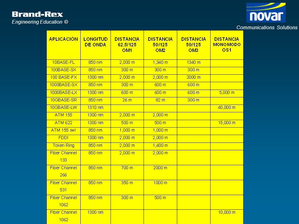
64
GIGABIT ETHERNET FIBRA ANCHO DE BANDA DISTANCIA MHz.km m
850/1300 nm nm 1300nm 62.5/ / 62.5/ / 50/ / 50/ / IEEE 802.3z aprobado el 25 de Junio de 1998

65
LED vs. Laser para Multimodo
Velocidad máxima de transmisión de un LED ~ 622 Mbps Las velocidades de Gigabit requieren lasers ¿Porqué no utilizar entonces monomodo…?

66
VCSEL Laser de Emisión por superficie de cavidad vertical (Vertical Cavity Surface Emitting Laser - VCSEL) Similar al Laser Fabry-Perot, pero… Reduce drásticamente el coste de los lasers acercandolos a los LEDs Disponible sólo en 850 nm

67
Pero… ¿Qué sucede si utilizamos Laser con fibra multimodo?

68
Laser vs. LED Núcleo saturado:Todos los modos transmiten LED
Laser/VCSEL Rayo en el centro del núcleo: Sólo se excitan algunos modos

69
En Teoría... Si sólo excitamos unos pocos modos, tendremos menor dispersión y mayor ancho de banda.

70
Differential Mode Delay
Earlier Delay, in picoseconds Later Scan across the fibre core in two micron steps Earlier Delay, in picoseconds Later

71
Differential Mode Delay
Pulso Recibido Pulso de Entrada Potencia 400 800 1200 1600 400 800 1200 1600 Tiempo (ps) Tiempo (ps)
 Tiempo (ps)")
72
Nuevas Fibras Multimodo Optimizadas para Laser
Son 50/125 Differential Mode Delay reducido por mejoras en los procesos de fabricación. Elevado Ancho de Banda en 1ª Ventana MHz Necesarias para 10GbE

73
NUEVAS PROPUESTAS PARA FIBRA DE ISO 11801
ISO ª Ed PROPONE ‘CLASES’ DE FIBRA PARA DIFERENTES APLICACIONES

74
ISO 11801 2ª Ed. Tipos de Fibra Optica
Ancho de Banda (MHz-Km) Clase Optica Tipo de Fibra Núcleo Saturado (LED) Efectivo (LASER) 850 1300 OM1 62.5/125 200 500 ND OM2 50/125 OM3 1500 2000
 Clase Optica. Tipo de Fibra. Núcleo Saturado (LED) Efectivo. (LASER) OM / ND. OM2. 50/125. OM")
75
ISO 11801 2ª Ed. Clases de Fibra Optica
Distancia (M) 300 500 2000 10 OM1 100 1000 OM2 OS1 10000 OM3 Velocidad de Transmisión (Mbps)
 OM OM2. OS OM3. Velocidad de Transmisión (Mbps)")
76
CABLES DE FIBRA OPTICA Brand-Rex Ltd

77
CONSTRUCCION TIPICA DE FIBRA
Revestimiento 125um Núcleo Protección primaria 250um Fibra óptica con protección primaria

78
PROTECCION AJUSTADA el tubo holgado de 500 um es el volition
Protección primaria 250um Portección intermedia de Silicona hasta 410 um Núcleo 50, 62.5 o monomodo Protección exterior de Nylon hasta 900 um (600 um para SFF) Tubo holgado de PVC 500 um / 900 um el tubo holgado de 500 um es el volition 600 um para los cables asociados a los conectores SFF Protección exterior de PVC hasta 900um Revestimiento 125um
 Tubo holgado de PVC. 500 um / 900 um. el tubo holgado de 500 um es el volition. 600 um para los cables asociados a los conectores SFF. Protección exterior de PVC. hasta 900um. Revestimiento 125um.")
79
CONSTRUCCIÓN DEL CABLE
Protección de la fibra Elementos de refuerzo Barreras anti humedad Armaduras Cubiertas

80
PROTECCION AJUSTADA Latiguillo óptico Brand-Rex Ltd Fibras de aramida
fibra de protección ajustada 900 um Cubierta exterior LSF/0H 2.8mm dia Latiguillo óptico

81
Cubierta exterior LSF/0H
PROTECCION AJUSTADA Capa de fibras de aramida Brand-Rex Ltd Cubierta exterior LSF/0H Hasta 24 fibras de 900 um de 2 a 12, solo aramida de 16 a 24 elemento central RBG con mas de 12, se repiten colores con una franja negra Cable de enlaces

82
CABLES DE PROTECCIÓN HOLGADA
Unitubo - Un solo tubo Elementos de refuerzo alrededor del tubo central 24 fibras máximo (Brand-Rex 96 fibras) Multiples tubos Elemento central de refuerzo Seis o mas tubos rellenos de gel enrrollados helicoidalmente alrededor del elemento central Hasta 144 fibras como estandar
 Multiples tubos. Elemento central de refuerzo. Seis o mas tubos rellenos de gel enrrollados helicoidalmente alrededor del elemento central. Hasta 144 fibras como estandar.")
83
capa de hilos de aramida como elemento de refuerzo
UNITUBO capa de hilos de aramida como elemento de refuerzo Brand-Rex Ltd cubierta exterior LSF/OH hasta 96 fibras de proteccion primaria en un tubo relleno de gel Cable Universal

84
MULTITUBO Cable dieléctrico de núcleo seco para ducto
Cubierta de polietileno elemento central central de refuerzo de RBG Brand-Rex Ltd 6 tubos rellenos de gel enrrollados helicoidalmente alrededor del elemento central conteniendo hasta 24 fibras cada uno Cintas o fibras bloqueadoras para ductos, bandejas exteriores oo aéreos si se cose a un soporte de catenaria. No lleva gel de relleno, más fácil de trabajar Cable dieléctrico de núcleo seco para ducto

85
MULTITUBO Cable con armadura de hilos de acero
cubierta exterior de polietileno cubierta de polietileno relleno de gel hidrofugo elemento central de acero Brand-Rex Ltd 6 tubos rellenos de gel conteniendo hasta 24 fibras cada uno barrera de aluminio Cinta de papel armadura de hilos de acero galvanizado Cable con armadura de hilos de acero para enterramiento directo

86
CONECTORES ÓPTICOS

87
DIAGRAMA DE UN CONECTOR
FERRULE CUERPO CASQUILLO DE CRIMPADO PROTECTOR DEL CABLE Depending on the manufacturer of the connector there may be more than one size of crimp ring to allow for different sizes of ruggedised cord. There may also be a small polypropylene tube which is used for terminating the connector to tight buffered fibre only. Connectors SHOULD ONLY be fitted to tight buffered or ruggedised cord fibres and NOT to primary coated fibres. In cases of doubt contact Brand-Rex for clarification.

88
ADAPTADOR SC ADAPTADOR ST
ADAPTADORES Dos conectores ópticos se conectan utilizando un pequeño accesorio llamado de múltiples formas: las mas usuales son “adaptador” y “acoplador”. The “uniter” or “adaptor” is usually bulkhead mounted in a patch panel. ADAPTADOR SC ADAPTADOR ST

89
ENFRENTAMIENTO En realidad pretendemos alinear los núcleos de las dos fibras. La concentricidad es fundamental: Núcleo-Revestimiento Revestimiento-Capilar Capilar-Ferrule Ferrule-Guías de alineamiento

90
Conectores Opticos MT-RJ ST SC LC

91
DISEÑO DE ENLACES OPTICOS

92
PARAMETROS DE ENLACES OPTICOS ISO/EN
MULTIMODO MONOMODO Parametro 850 nm nm nm nm Atenuacion dB/km max max n/a n/a BW MHz.km min min n/a n/a Conector 0.75 max max max max Perdidas Insercion Perdidas Retorno min min min min : These are the MAXIMUM permissible losses in a fibre optic system, and can be measured with either an OTDR or a LS & PM. Perdidas de empalme max max max max

93
PARAMETROS DE ENLACES OPTICOS ISO/EN
Atenuacion dB Subsistema de Longitud cableado máxima Multimodo Monomodo 850 nm nm nm nm Horizontal m OF m Troncal edificio m OF m Troncal campus m OF m ISO nd Ed en ROJO

94
Cálculo de pérdidas Troncal de Campus Latiguillo adaptador conector
panel repartidor cable km conectores cable x 3.5 empalme empalme Pérdidas totales = (1.9 x 3.5) = 8.45 dB a 850 nm Perdidas de enlace permitidas = 8.5dB
 = 8.45 dB a 850 nm. Perdidas de enlace permitidas = 8.5dB.")
95
ISO 11801 2ª Ed. Clases de Fibra Optica
Distancia (M) 300 500 2000 10 OM1 100 1000 OM2 OS1 10000 OM3 Velocidad de Transmisión (Mbps)
 OM OM2. OS OM3. Velocidad de Transmisión (Mbps)")
Presentaciones similares


>")


>")

