Descargar la presentación
La descarga está en progreso. Por favor, espere

1
Master Training Mexico 2010
SF3000 Master Training Mexico 2010

2
Monitores Actuales GreenStar™
GreenStar™ Systems Review Provide an overview of the available GreenStar displays. Please use the following resource for discussion about GreenStar™ capabilities: GreenStar Display Compatibility Chart (Available via the Ag Sales Manual- Key Features link for the 2600). As of April 28th the chart has the following discrepancies: - GS does have an optional display control - GS is now compatible with the Lightbar as of the latest software version. The original display is compatible with SprayStar™ SeedStar™ and SpreadStar™ but, not the newer versions for example SeedStar2. (all displays are compatible) - Be sure to mention the GreenStar™ Lightbar as an option for parallel tracking.
. As of April 28th the chart has the following discrepancies: - GS does have an optional display control. - GS is now compatible with the Lightbar as of the latest software version. The original display is compatible with SprayStar™ SeedStar™ and SpreadStar™ but, not the newer versions for example SeedStar2. (all displays are compatible) - Be sure to mention the GreenStar™ Lightbar as an option for parallel tracking.")
3
Receptor StarFire™ 3000 StarFire™ Receivers Review
Instructor: Please review the key features for each receiver. Please reference the AG Sales Manual for supplemental information. StarFire™ 300: The StarFire™ 300 receiver is an entry-level Global Positioning System (GPS) with an integrated antenna for mounting on top of the cab. The receiver utilizes signals from the US-government operated Global Positioning System (GPS). The receiver is capable of receiving differential corrections via satellite to provide a more accurate position. In North America, the US provides the Wide Area Augmentation System (WAAS) differential corrections. The European Union provides similar data through EGNOS. It provides position, velocity, and time (PVT) updates to the GreenStar system. The PVT data is made available through the CAN interface and also through the RS232 interface using standard NMEA format. In addition, the unit provides a simulated radar speed output. The StarFire™ 300 is capable of outputting a simulated radar speed for rate controllers and planter monitors. StarFire 300 is a versatile WAAS receiver featuring 13-in. pass-to-pass accuracy. It is a perfect solution for applications such as: Parallel Tracking™ (manual guidance) Documentation Field Doc™ Harvest Doc™ Map-Based Prescriptions StarFire 300 limitations : No terrain compensation No access to SF1, SF2, or RTK Cannot perform AutoTrac™ Swath Control Pro™ is not recommended Requires Software Update or newer for compatibility with the Original GreenStar™ Display StarFire™ iTC Receiver The StarFire™ iTC Receiver is a twelve channel, dual-frequency differential GPS receiver with integrated Terrain Compensation (iTC). The twelve channel engine picks up signals from the Global Positioning System satellites and from the John Deere differential correction network. Using these signals, the StarFire™ receiver can pinpoint it’s location with exceptional accuracy. Discuss the L1 and L2 frequencies: L1C is a civilian-use signal, to be broadcast on the same L1 frequency ( MHz) that currently contains the coarse-acquisition signal used by all current GPS users. Civilian L2 (L2C) The L2C signal broadcast on the L2 frequency ( MHz). It is transmitted by all block IIR-M and later design satellites. The L2C signal is tasked with providing improved accuracy of navigation, providing an easy-to-track signal, and acting as a redundant signal in case of localized interference. The immediate effect of having two civilian frequencies being transmitted from one satellite is the ability to directly measure, and therefore remove, the ionospheric delay error for that satellite.
 with an integrated antenna for mounting on top of the cab. The receiver utilizes signals from the US-government operated Global Positioning System (GPS). The receiver is capable of receiving differential corrections via satellite to provide a more accurate position. In North America, the US provides the Wide Area Augmentation System (WAAS) differential corrections. The European Union provides similar data through EGNOS. It provides position, velocity, and time (PVT) updates to the GreenStar system. The PVT data is made available through the CAN interface and also through the RS232 interface using standard NMEA format. In addition, the unit provides a simulated radar speed output. The StarFire™ 300 is capable of outputting a simulated radar speed for rate controllers and planter monitors. StarFire 300 is a versatile WAAS receiver featuring 13-in. pass-to-pass accuracy. It is a perfect solution for applications such as: Parallel Tracking™ (manual guidance) Documentation. Field Doc™ Harvest Doc™ Map-Based Prescriptions. StarFire 300 limitations : No terrain compensation. No access to SF1, SF2, or RTK. Cannot perform AutoTrac™ Swath Control Pro™ is not recommended. Requires Software Update or newer for compatibility with the Original GreenStar™ Display. StarFire™ iTC Receiver The StarFire™ iTC Receiver is a twelve channel, dual-frequency differential GPS receiver with integrated Terrain Compensation (iTC). The twelve channel engine picks up signals from the Global Positioning System satellites and from the John Deere differential correction network. Using these signals, the StarFire™ receiver can pinpoint it’s location with exceptional accuracy. Discuss the L1 and L2 frequencies: L1C is a civilian-use signal, to be broadcast on the same L1 frequency ( MHz) that currently contains the coarse-acquisition signal used by all current GPS users. Civilian L2 (L2C) The L2C signal broadcast on the L2 frequency ( MHz). It is transmitted by all block IIR-M and later design satellites. The L2C signal is tasked with providing improved accuracy of navigation, providing an easy-to-track signal, and acting as a redundant signal in case of localized interference. The immediate effect of having two civilian frequencies being transmitted from one satellite is the ability to directly measure, and therefore remove, the ionospheric delay error for that satellite.")
4
StarFire™ 3000 – Mejoras del Receptor
Compensación del Terreno Mejorada Mejor adquisición de satelites Mejor resistencia a la “sombra” Aumento de disponibilidad de satelites Activaciones En-el-Aire StarFire™ 3000 Receiver Enhancements There are 4 features the SF3000 receiver has that have been improved since the iTC receiver. Improved terrain compensation Better satellite acquisition Better resistance to shading Increased satellite availability Over-the-Air Activations

5
StarFire™ 3000 vs. StarFire™ iTC
Discuss key feature differences between the iTC and the This is a high-level summary. The technical aspects of these features will be discussed throughout the course material. This chart is available in the student workbook. Key items: Terrain Compensation Satellite Constellations GLONASS Activations are included (RTK for original release)
")
6
Módulo de Compensación de Terreno (TCM)
Declive (grados) Error Esperado (Pulgadas) 1 2.2 2 4.3 3 6.4 4 8.6 5 10.8 6 12.9 7 15.1 8 17.3 9 19.5 10 21.7 Errores Potenciales sin TCM Con TCM Sin TCM 6
 Error Esperado. (Pulgadas) Errores Potenciales sin TCM. Con TCM. Sin TCM. 6.")
7
Teoría de Compensación de Terreno (Receptor iTC)
Terrain Compensation Operational Theory (iTC) Instructor note: Use discretion as you discuss the following information. It may not be necessary to provide this level of detail to students unless asked specifically. The iTC uses Roll and Yaw to determine its position relative to the earth’s surface. The iTC uses a combination of gyros and accelerometers to calculate vehicle dynamics which are then used in the TCM. Basically the gyros measure movement in the horizontal plane (yaw) and accelerometers measure roll. The accelerometers do indeed monitor ambient temperature and use that information to compensate for changes in resistance in the circuits. What it amounts to is that the receiver has a table of different correction values based on temperature fluctuation for the electrical signals it uses. So it can say “Air temp is X degrees, according to this variance curve my signal from the accelerometer will be affected by Y milli-volts” and apply that correction. The TCM takes all of this and translates the receiver position into an actual position on the ground. This is where the triangles come in and where the familiar explanation of the TCM starts. If a tractor is sitting on a sidehill of a certain slope (calculated above), it is a simple trig function to transpose the receiver’s position to a centerline on the ground under the vehicle. Of course, the vehicle is moving, so both the dynamics calculations and the subsequent adjusted position calculations are iteratively revised to keep up with the changing conditions. The gyros are not temp-compensated; since they have a constant heading that they are supposed to be aiming at as the tractor moves, the receiver can determine if they’re reporting a yaw that’s consistently off by a certain amount and remove that bias in its position calculations. Also, some of this information is used elsewhere in addition to the TCM. Yaw and more importantly yaw rate are measurements that AT has the ability to react to. So if the AT controller sees that yaw rate changes significantly, it will more than likely see a heading and/or tracking error before very long. It is AT’s way of sort of peeking around the corner and anticipating what will happen next. Ask / discuss the following questions: Question: How does the TCM impact AutoTrac™ accuracy? Answer: It compensates for cab roll due to rough terrain or side slopes. Question: Is it important to properly calibrate the TCM? Why? Answer: It is crucial that the TCM is set up and calibrated properly. An improperly calibrated TCM will change the effective location of the StarFire receiver on the cab, causing skips or overlaps as you travel through the field.
 Instructor note: Use discretion as you discuss the following information. It may not be necessary to provide this level of detail to students unless asked specifically. The iTC uses Roll and Yaw to determine its position relative to the earth’s surface. The iTC uses a combination of gyros and accelerometers to calculate vehicle dynamics which are then used in the TCM. Basically the gyros measure movement in the horizontal plane (yaw) and accelerometers measure roll. The accelerometers do indeed monitor ambient temperature and use that information to compensate for changes in resistance in the circuits. What it amounts to is that the receiver has a table of different correction values based on temperature fluctuation for the electrical signals it uses. So it can say Air temp is X degrees, according to this variance curve my signal from the accelerometer will be affected by Y milli-volts and apply that correction. The TCM takes all of this and translates the receiver position into an actual position on the ground. This is where the triangles come in and where the familiar explanation of the TCM starts. If a tractor is sitting on a sidehill of a certain slope (calculated above), it is a simple trig function to transpose the receiver’s position to a centerline on the ground under the vehicle. Of course, the vehicle is moving, so both the dynamics calculations and the subsequent adjusted position calculations are iteratively revised to keep up with the changing conditions. The gyros are not temp-compensated; since they have a constant heading that they are supposed to be aiming at as the tractor moves, the receiver can determine if they’re reporting a yaw that’s consistently off by a certain amount and remove that bias in its position calculations. Also, some of this information is used elsewhere in addition to the TCM. Yaw and more importantly yaw rate are measurements that AT has the ability to react to. So if the AT controller sees that yaw rate changes significantly, it will more than likely see a heading and/or tracking error before very long. It is AT’s way of sort of peeking around the corner and anticipating what will happen next. Ask / discuss the following questions: Question: How does the TCM impact AutoTrac™ accuracy Answer: It compensates for cab roll due to rough terrain or side slopes. Question: Is it important to properly calibrate the TCM Why Answer: It is crucial that the TCM is set up and calibrated properly. An improperly calibrated TCM will change the effective location of the StarFire receiver on the cab, causing skips or overlaps as you travel through the field.")
8
Teoría de Compensación de Terreno (StarFire™ 3000)
Terrain Compensation Theory (StarFire™ 3000) The SF3000 will respond faster and more accurately to changes in terrain Inertia Measuring Unit (IMU): Works with the TCM to provide better accuracy iTC: Asks if the vehicle is level (yes/no answer) SF3000: Asks if it is level or not and by how much it is off to compensates for it. The StarFire™ 3000 includes the calculation of Pitch during the calibration procedure. It is this additional measurement that requires the machine to be on flatter ground than an iTC. It will be more sensitive to ground conditions than the iTC. 3 axis terrain compensation and calibration procedure picky/more sensitive – refer to OM as need to complete process in the steps. If calibration has not been done properly , a pop-up screen will appear on the GS2 letting the user know what they did wrong and how to correct it. Hi-low voltage error code will also be displayed iTC only measures Roll and Yaw 3000 measures Pitch, Roll, and Yaw
 The SF3000 will respond faster and more accurately to changes in terrain. Inertia Measuring Unit (IMU): Works with the TCM to provide better accuracy. iTC: Asks if the vehicle is level (yes/no answer) SF3000: Asks if it is level or not and by how much it is off to compensates for it. The StarFire™ 3000 includes the calculation of Pitch during the calibration procedure. It is this additional measurement that requires the machine to be on flatter ground than an iTC. It will be more sensitive to ground conditions than the iTC. 3 axis terrain compensation and calibration procedure picky/more sensitive – refer to OM as need to complete process in the steps. If calibration has not been done properly , a pop-up screen will appear on the GS2 letting the user know what they did wrong and how to correct it. Hi-low voltage error code will also be displayed. iTC only measures Roll and Yaw measures Pitch, Roll, and Yaw.")
9
Adquisición de Satelites y Resistencia a la “sombra”
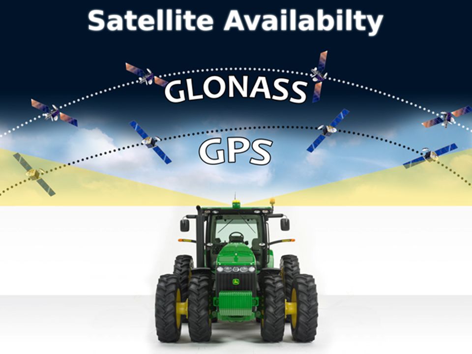
Actualizaciones en Hardware y software Nueva antena interna de GPS Vista de satelites desde 5 grados arriba del horizonte Metodo de adquisición de satelites actualizada Ultimas actualizaciones minimiza poteciales errores y perdidas de señal Satellite Acquisition and Shading Resistance New hardware and software technology allow the sf3000 to acquire satellites and resist shading better than what iTC customers were experiencing. The SF3000 receiver has a lower look angle off the horizon allowing the SF3000 to use satellites in its solution that were once not available with the iTC. Having more satellites in the solution also mitigates the risk for shading issues due to tree lines or other structures. -Updated satellite tracking methods -Latest software mitigates potential for errors and signal loss

11
Visual for the lower look angle

12
¿Qué es GLONASS? Operado y propiedad del Gobierno Ruso.
SF3000 utilizará los satélites GLONASS en correcciones RTK. Ofrece acceso a más puntos de referencia en cualquier momento. La constelación tiene 24 satélites orbitando alrededor de la tierra. What is GLONASS WAAS – Not GLONASS compatible StarFire SF1, SF2 – Not GLONASS compatible GLONASS does not necessarily improve accuracy, but it does improve the satellite availability during the times when the satellite availability is low StarFire iTC is not GLONASS compatible **Side note: GLONASS -- Russian Version of GPS, restoration project from the cold war. There are18 satellites operational today and the Goal is to have 24 satellites by In order for GLONASS to be effective, BOTH the vehicle and differential correction source must be GLONASS compatible.

13
TCM TCM – Terrain Compensation Module
Esta función es una calibración previa a la operación, el sistema nos da un ángulo el cual indica que tan inclinada esta la antena con respecto a la horizontal del suelo y con esto podemos estar seguros que la corrección se da sobre el movimiento a la altura del suelo, no a la altura de la antena, que es mayor.

14
Activations En-el-aire
Puedes activar SF1 a SF2 o RTK sin el codigo de 26 digitos Solicita la activación a través del sitio de Stellar Support y determina una hora Se carga a través de satelites El receptor debe estar encendido y en busca de satélites Solo se envía una vez la activación Si no se activa, emitirá una advertencia Over-the-Air Activations Activate SF2 Ready or RTK without codes Customer enters the activation request through the Stellar Support website and designates what time activation should be sent Loaded through satellite at a time designated by the customer Receiver must be powered up and tracking when activation is sent Stellar only sends it once, so if customer gets sidetracked and doesn’t get the receiver going he will have to do it over again If unsuccessful, it should throw a warning Is only for accuracy activations, not for any display-housed applications (AT, SWP, SCP, etc)
")
15
Precisión de Señales RTK +/- 1 pulgada SF2 +/- 4 pulgadas SF1
WAAS +/- 13 pulgadas SF1 +/- 10 pulgadas SF2 +/- 4 pulgadas RTK +/- 1 pulgada Signal Accuracies Discuss the available signal accuracies. SF1 and SF2 accuracy levels are described on a pass to pass basis measured at the receiver, within 15 minutes, 95 percent of the time. A pass to pass accuracy of +/- 10 inches could result in 20 inches of total error. List appropriate field operations for each signal accuracy WAAS: Parallel Tracking™ and documentation applications. SF1: Broad acre seeding (non row-crop guidance applications) Broad acre spraying Tillage Air Seeding SF2: Planting with Swath Control Pro™ Row crop operations RTK: Row Crop operations Strip till Bedding
 Broad acre spraying. Tillage. Air Seeding. SF2: Planting with Swath Control Pro™ Row crop operations. RTK: Row Crop operations. Strip till. Bedding.")
16
StarFire™ y RTK StarFire™ and RTK Section Introduction slide

17
Real Time Kinematics (RTK)
GPS Real Time Kinematics StarFireTM RTK provides highly accurate corrections to the AutoTracTM guidance system. It utilizes a local, ground-based reference station that transmits the high-accuracy corrections to a vehicle StarFire receiver via RTK radios. Because of the proximity of the base station to the vehicle, nearly all GPS drift is eliminated, and the position is highly repeatable. In order for the base-station signal to reach the vehicle, a direct line of sight is required. Base Station Operation 5 satellites are needed to engage RTK 4 satellites are needed to stay engaged in RTK Vehicle Operation 50% of the position solution comes from the satellites 50% of the position solution comes from the base station correction data Both are equally important Software design If there not enough satellites available, RTK will not engage If there are enough satellites, but the correction information is bad, RTK will not engage Locked on to 6 satellites, but RTK will not engage May not be receiving L2 data from 2 of the 6 satellites, so RTK will not engage Base Station Transmits signal at 5 Hz (5 correction packets per second) (900 MHz only) (450Mhz radio sends corrections 2 x second) Vehicle only needs 1 packet every 2 seconds to stay in RTK 1 packet out of 10 is 10% Data Received can be as low as 10% without any problems Data Received Rate DOES NOT affect Accuracy!! Effective range is 12 miles. Vehiculo Base Station Sub inch accuracy
 (900 MHz only) (450Mhz radio sends corrections 2 x second) Vehicle only needs 1 packet every 2 seconds to stay in RTK. 1 packet out of 10 is 10% Data Received can be as low as 10% without any problems. Data Received Rate DOES NOT affect Accuracy!! Effective range is 12 miles. Vehiculo. Base Station. Sub inch accuracy.")
18
Revición Red StarFire™
Conexión a Tierra StarFire Network Review John Deere is proud to be the only company in the precision ag market to offer its own differential corrections through the StarFire Network. It’s true that everyone uses the same raw GPS, but differential corrections is a different story. Because John Deere owns its own network of reference stations and processing hubs, you don’t have to rely upon WAAS or go to a third-party differential corrections service. How the StarFire Network works Seven reference stations throughout the U.S., four in Europe, three in Australia, and three in South America, receive signals from the GPS satellites. Information is sent from the reference stations to the processing hubs in Moline and Redondo Beach, CA, where corrections are generated. The corrections are then uplinked via the Land Earth Station Uplink to 3 Inmarsat satellites, which distribute the correction signal to the StarFire receivers throughout the world. GPS is being told where it is at uses Inmarsat for corrections Instructor knowledge: **We do not own the sats, we only own Reference stations and processing hubs.*** The following is for instructor knowledge… instructor discretion should be used when discussing the following information: GSBAS Importantly, GSBAS systems provide absolute positioning, meaning they do not determine position relative to some fixed point of the Earth’s surface. Instead, they determine a position within a space-based reference frame, thus they may also be considered to be within the Space Domain group. Satellite communication links are used for some dGPS systems, so the term GSBAS does not relate to the communication link used but instead describes the nature of the corrections, i.e. that they are for the satellites. This class includes: Standalone GPS WAAS EGNOS MSAS StarFire™ Augmentation for Standalone GPS consists of satellite orbit and clock updates which are generated by the GPS Ground Control Segment and distributed to the user with an ionospheric model in the GPS signal structure. It is this basic principle of determining each error source instead of amalgamating them which distinguishes GSBAS from dGPS. Figure 1 shows the GSBAS and StarFire™ service areas and the global reference stations that are used for the StarFire™ system. The reference network infrastructure, quality of hardware, algorithm sophistication, and the speed at which this is accomplished all contribute to the robust positioning accuracy attained by the user. METHODOLOGY The StarFire Network is a major advance from earlier ground based augmentation systems because it considers each of the GPS satellite signal error sources independently. GPS satellite orbit and clock corrections are calculated from a global tracking network of dual frequency receivers. These corrections are transmitted via Inmarsat satellite links direct to StarFire receivers, resulting in minimal data latency and worldwide operation from 75 degrees North to 75 degrees South. All StarFire receivers use a dual frequency GPS receiver that measures the ionospheric delay for each satellite. Tropospheric zenith delays are calculated from a multi-state time and position model aided by redundant satellite observables. RELIABILITY Redundant data links, geographically separated processing hubs and dual satellite uplink equipment ensure continuous reliable positioning. The system is inherently robust with the ability to calculate a full set of corrections even if multiple reference stations were to become unavailable. A global network of dual frequency GPS receivers provides raw data every second via reliable redundant data links to two network processing centers located in Torrance, (S.W., USA) and Moline, (N.E., USA). These receivers are tied to the latest realization of the International Terrestrial Reference Frame (ITRF) coordinate system. StarFire’s primary time reference is coupled to the International Atomic Time standard. The network is a fully automated continuously self-monitoring system overseen around the clock by StarFire Network operators. The GSBAS algorithms developed by NavCom are based on technology licensed from NASA’s Jet Propulsion Laboratory. Orbit and clock corrections from both processing centers are distributed via dedicated circuits with multiple communication backups to three Inmarsat satellite uplink stations. An independent network of StarFire user equipment continuously monitors system accuracy to ensure maximum reliability. Staciones StarFire de Referencia Centro de Procesamiento
 and Moline, (N.E., USA). These receivers are tied to the latest realization of the International Terrestrial Reference Frame (ITRF) coordinate system. StarFire’s primary time reference is coupled to the International Atomic Time standard. The network is a fully automated continuously self-monitoring system overseen around the clock by StarFire Network operators. The GSBAS algorithms. developed by NavCom are based on technology licensed from NASA’s Jet Propulsion Laboratory. Orbit and clock corrections from both processing. centers are distributed via dedicated circuits with multiple communication backups to three Inmarsat satellite uplink stations. An independent network of StarFire user equipment continuously monitors system accuracy to ensure maximum reliability. Staciones StarFire de Referencia. Centro de Procesamiento.")
19
Repetidores Repeaters
Repeater radios can be used to improve or extend base station signal coverage around obstacles such as trees or rolling terrain. More than 1 repeater can be used with one base station, but they cannot receive signal from each other in a “daisy chain” configuration. In order to operate, a repeater must be connected to a 12-volt power source. A repeater radio can also be used as a vehicle or base station radio; however, the receiver must have an RTK Activation. The 450MHz radio does not support the use of repeaters. A repeater consists of: 900-MHz RTK radio Wiring harness Mounting bracket NOTE: Repeaters do NOT extend the 12-mile accuracy range of a base station. Also, make sure that a vehicle cannot see more than 1 repeater at a time, or A-B line jumps may occur.

20
RTK Extend El tiempo que el RTK Extend dura depende de que tanto tiempo ha estado funcionando la estación base 15 min - 1 hora = 2 min de RTK-Extend Mas de 1 hora = 15 min de RTK-Extend RTK Extend Allows an operator to continue with RTK level accuracy for up to 15 minutes after RTK radio communication is lost. This feature is an industry exclusive Estación Base Vehiculo

21
Sistema de Monitoreo de Señal StarFire™
Rojo: Precisión Pobre No receomendado para usar las aplicaciones GreenStar. Valor PDOP mayor a 4.6 Menos de 5 satélites en solución Naranja AutoTrac™ para labranza Operaciones Gran Escala Valor PDOP entre Menor o igual a 5 satélites en solución * Usuarios de SF1 siempre verán el indicador naranja GreenStar™ Display Key Topics: Monitoring system theory of operation Variables that determine each signal rating Application / uses of this tool For more details, please reference the GS2 Guidance OM page Quick hitters: Poor accuracy variables (red): PDOP value greater than 4.6 Less than 5 satellites in solution Marginal accuracy variables (Orange): PDOP value between 3.5 and 4.5 Less than or equal to 5 satellites in solution Normal accuracy variables (Green): PDOP value less than 3.5 More than 7 satellites in solution Verde (RTK or SF2) Operaciones de Precisión Valor PDOP menor a 3.5 Mas de 7 satélites en solución
: PDOP value greater than 4.6. Less than 5 satellites in solution. Marginal accuracy variables (Orange): PDOP value between 3.5 and 4.5. Less than or equal to 5 satellites in solution. Normal accuracy variables (Green): PDOP value less than 3.5. More than 7 satellites in solution. Verde (RTK or SF2) Operaciones de Precisión. Valor PDOP menor a 3.5. Mas de 7 satélites en solución.")
22
Herramienta Predictora de Satelites
Escenario: Recibe una llamada de un cliente que se queja del deseméño del AutoTrac™. Esto parece estar sucediendo cuando opera cerca de lineas de arboles. Favor de usar la herramienta predictora de satélites para dar una respuesta adecuada. Sitio Web StellarSupport >> Quick Support menu >> Satellite Predictor Tool Satellite Predictor Tool Student activity: 20 minutes (If students are unable to access web-site the instructor should lead the activity.) - Break students into teams of 2. They should navigate to the satellite predictor tool via the stellarsupport website. The workbook will have additional information Students should record their responses in the workbook Discuss answers with class Scenario: You receive a call from a customer who complains about AutoTrac™ performance issues. This appears to happen only during the morning time when operating near tree lines. Use the Satellite Predictor Tool to answer the following questions. Scenario specifics: Instructor determined Customer location: Dates: Time of Day:
 - Break students into teams of 2. They should navigate to the satellite predictor tool via the stellarsupport website. The workbook will have additional information. Students should record their responses in the workbook. Discuss answers with class. Scenario: You receive a call from a customer who complains about AutoTrac™ performance issues. This appears to happen only during the morning time when operating near tree lines. Use the Satellite Predictor Tool to answer the following questions. Scenario specifics: Instructor determined. Customer location: Dates: Time of Day:")
23
StarFire™ 3000 – Estado Indicador LED
Estación Base Vehiculo Estado Apagado Receptor Apagado Parpadeo Rojo Bajo Voltaje: El sistema tiene menos de 9 volts Parpadeo Azul N/A Estudio Rápido: Correcciones transmitidas con menos de 5 satélites Fijo Azul Estudio Rápido: Correcciones transmitidas con al menos 5 satélites Parpadeo Verde Base Absoluta: Correcciones transmitidas con menos de 5 satélites Fijo Verde Base Absoluta: Correcciones transmitidas con menos de 5 satelites Adquiriendo Señal (Vehículos Solamente) Arreglo 2D/3D guardado debajo de la precisón ideal StarFire™ 3000 Status LEDs Discuss the StarFire™ 3000 Status LEDs. This chart is provided in the student workbook.
 Arreglo 2D/3D guardado debajo de la precisón ideal. StarFire™ 3000 Status LEDs. Discuss the StarFire™ 3000 Status LEDs. This chart is provided in the student workbook.")
24
Questions?

Presentaciones similares


 Noviembre de 2004.>")
 29 de julio de 2004.>")


