Descargar la presentación
La descarga está en progreso. Por favor, espere

1
Espectro Electromagnético, Telescopios, y Detectores
Luis F. Rodríguez, CRyA, UNAM, Morelia ¿Cómo obtenemos información los astrónomos? El espectro electromagnético Telescopios Detectores

2
¿Cómo puede obtener información el astrónomo sobre el Universo?
Para objetos muy “cercanos” (en nuestro Sistema Solar) contamos con la exploración directa y con la radar astronomía.
 contamos con la exploración directa y con la radar astronomía.")
3
Robot en Marte

4
Pero… La exploración directa sólo es aplicable a los objetos de nuestro Sistema Solar. Las naves espaciales mas rápidas viajan a unos 20 kilómetros por segundo, o sea que tardarían unos 50,000 años en llegar a la estrella más cercana, Proxima Centauri. Ya no digamos recorrer toda nuestra Galaxia o ir a otras galaxias.

5
Escalas del Universo

6
Hay otra manera “activa” de estudiar el Universo
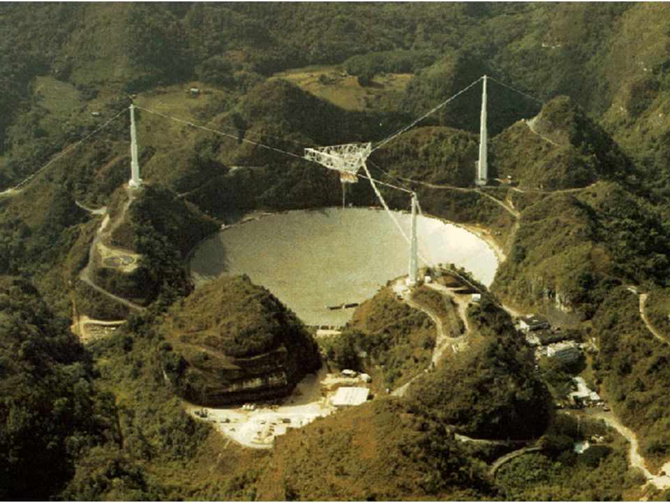
La radar astronomía. Con esta técnica se envían ondas de radio a cuerpos cercanos del sistema solar, donde rebotan y parte de ellas regresan al radiotelescopio que las envió.

7
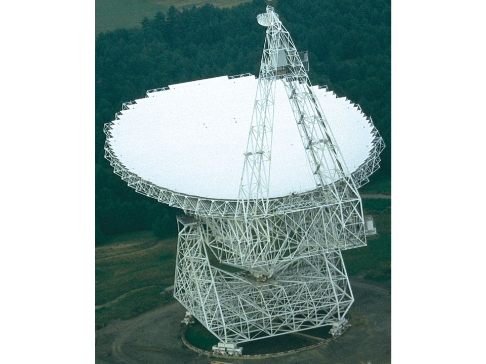
Radiotelescopio de Arecibo

8
Imágenes de un asteroide mediante radar astronomía
(el asteroide en si es emisor muydébil de ondas de radio)
")
9
¿Porqué la radar astronomía está tan limitada?
El flujo de fotones que recibimos de un cuerpo decrece como la distancia al cuadrado. En la radar astronomía la intensidad de la señal “rebotada” decae ¡como la distancia a la cuarta potencia!

10
D L

11
D F’

12
La mayoría de la astronomía se hace de manera “pasiva”
Detectamos partículas u ondas que se produjeron en el pasado por los objetos cósmicos estudiados. Por esto se dice que somos “observadores” y no “experimentadores”.

13
¿Cuáles son estos mensajeros del espacio?
Rayos cósmicos Neutrinos Ondas gravitacionales Pero en realidad, la mayor parte del trabajo observacional se hace mediante la detección de fotones, tambien conocidos como ondas electromagnéticas (dualidad partícula-onda)
")
14
Proyecto Auger Rayos Cósmicos

15
Neutrinos

16
Ondas gravitacionales
LIGO

17
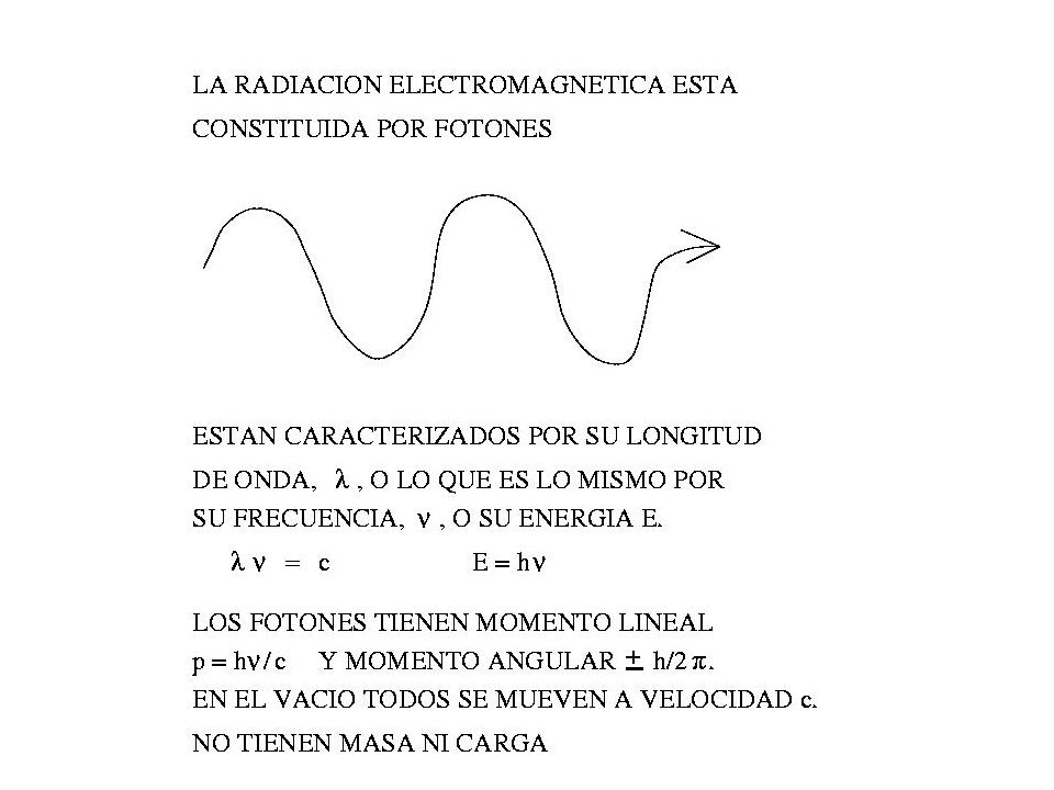
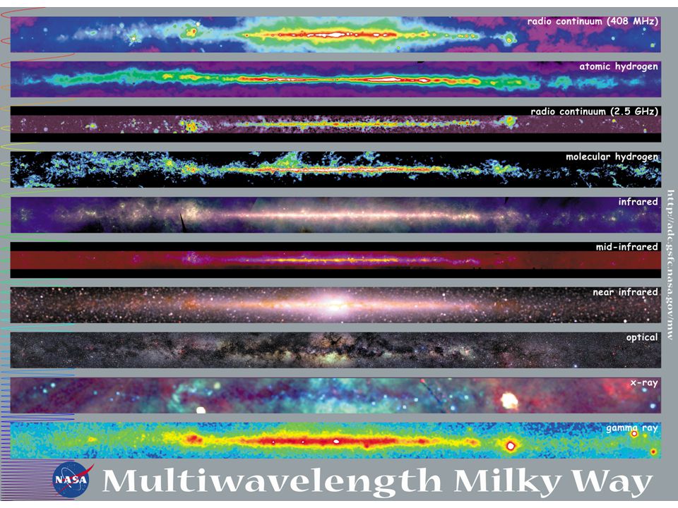
El espectro electromagnético

18
El espectro electromagnético en la vida diaria

19
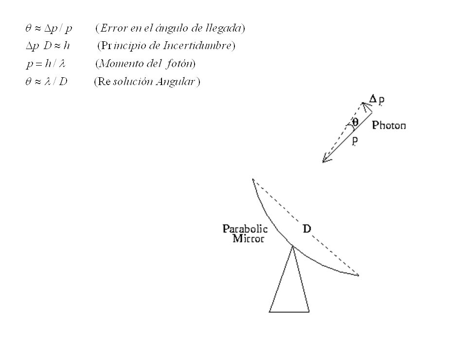
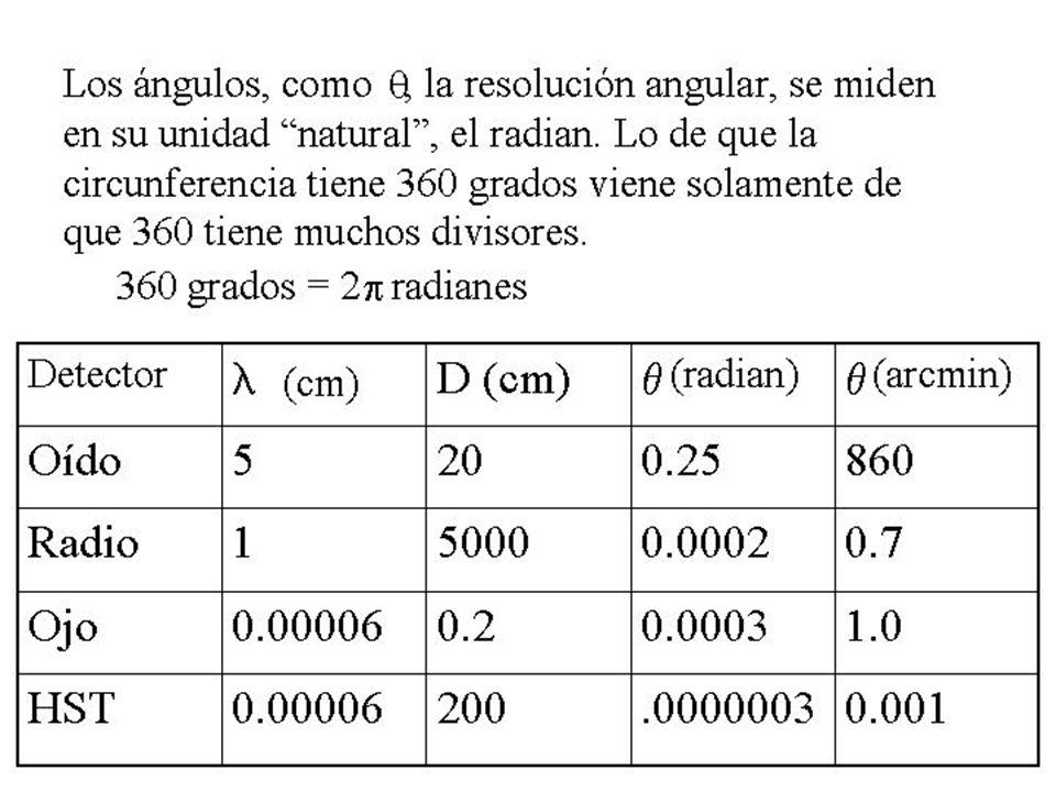
Para las ondas electromagnéticas:
= longitud de onda = frecuencia c = velocidad de la luz

20
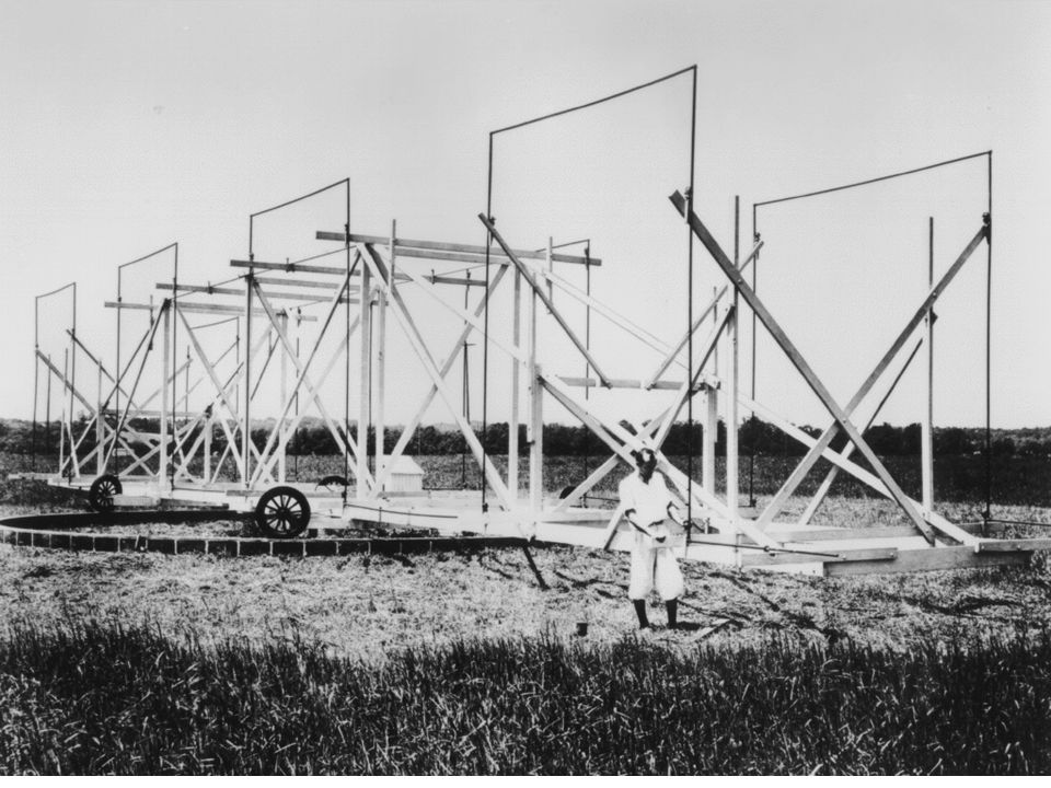
En la radioastronomía se mide la componente eléctrica del campo electromagnético, la cual se amplifica mediante equipo electrónico. En contraste, en el visible o en los rayos X, se detecta el fotón como si fuera “partícula”.

25
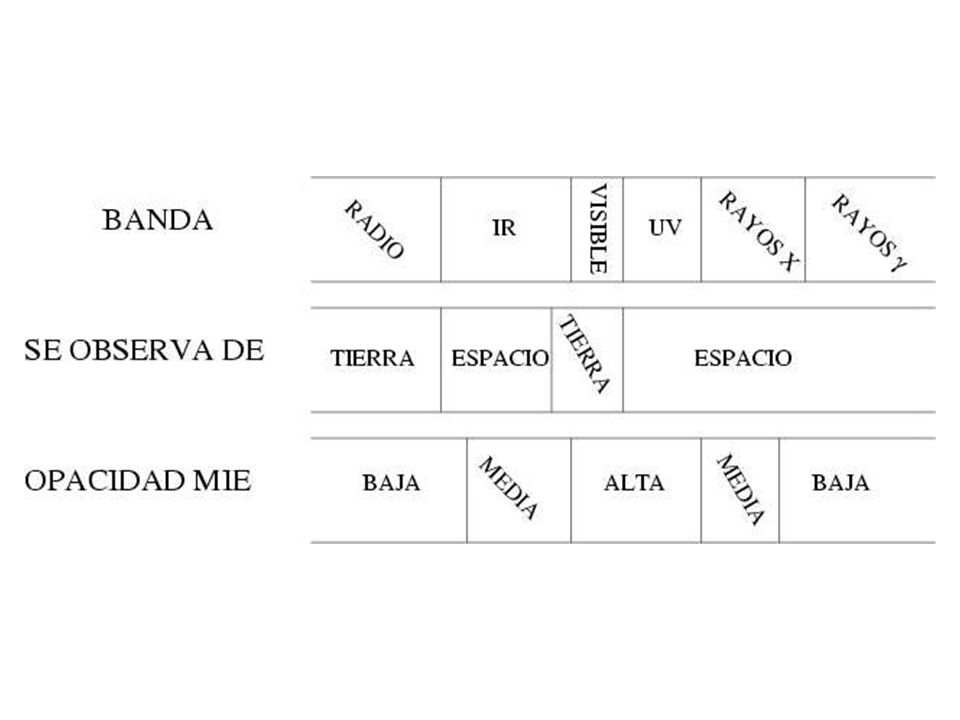
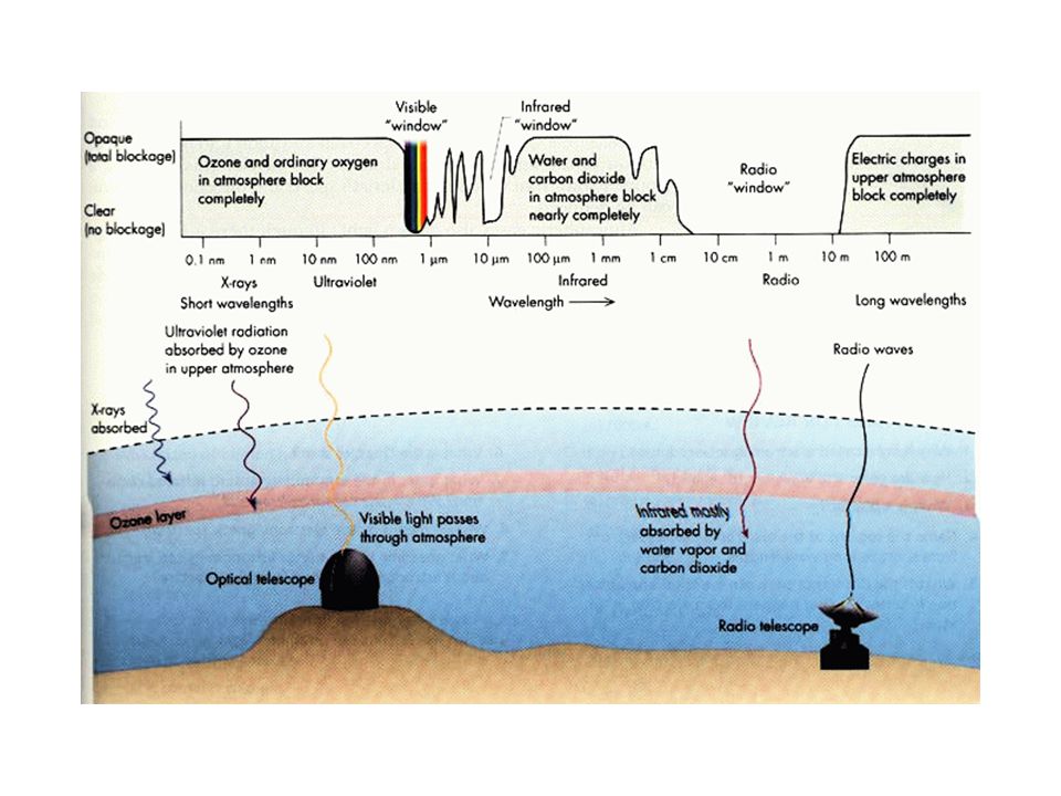
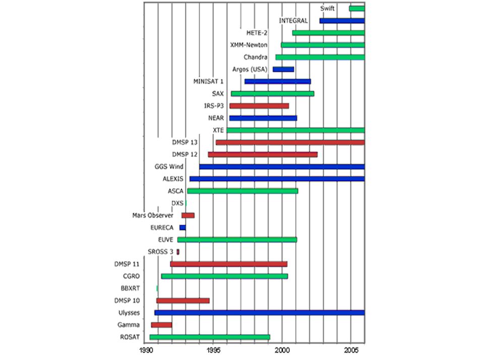
Debido a que nuestra atmósfera es opaca a los rayos X y rayos g, esta astronomía ha estado siempre ligada con la industria aeroespacial En otras palabras, la astrofísica de altas energías sólo se pudo comenzar a desarrollar en la década de los 1950´s.

26
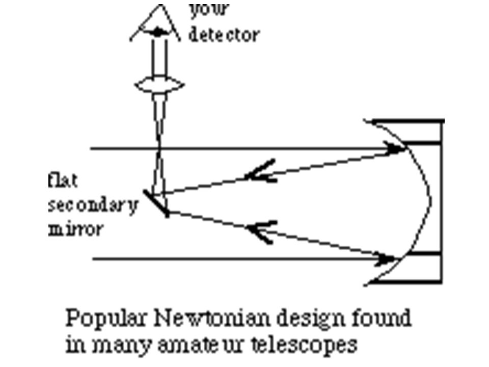
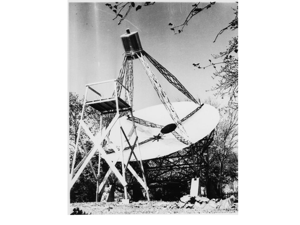
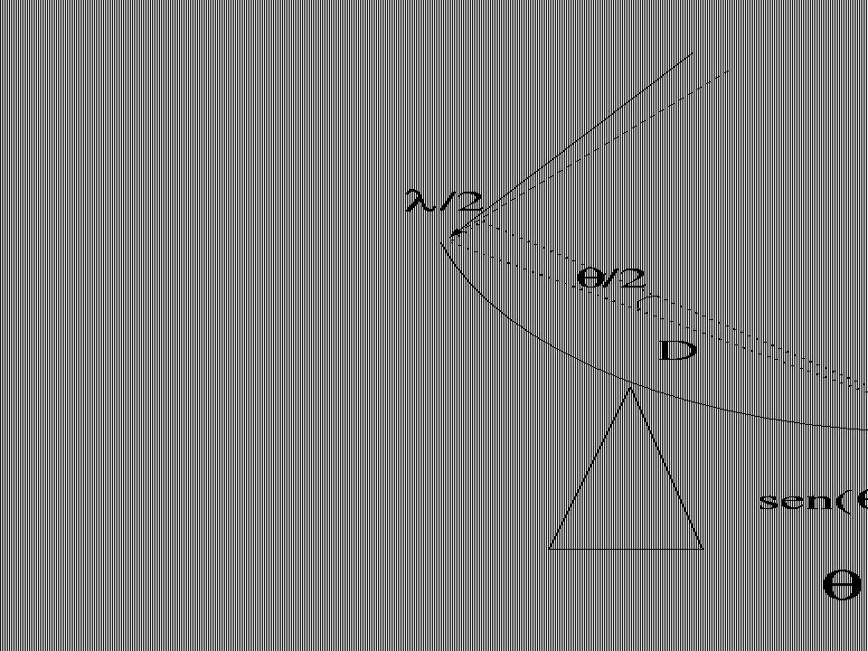
Telescopios Del radio al ultravioleta, la mayoría de los telescopios son superficies parabólicas. ¿Porqué?

27
La parábola tiene dos propiedades cruciales:
Concentra los rayos en el foco (aumentando la sensitividad). El camino recorrido por los rayos es el mismo (de modo que las ondas llegan en “fase”).
. El camino recorrido por los rayos es el mismo (de modo que las ondas llegan en fase ).")
28
Signal path:

47
Hasta los años 1960s la resolución angular de los telescopios de rayos X era muy mala.
Esto se debía a que los rayos X no rebotan en un espejo, sino que lo penetran. Sin embargo, los rayos X sí rebotan cuando llegan al espejo casi rasantes. Giacconi propuso el concepto de los espejos cilíndricos embebidos en los que los rayos X llegaban rasantes.

48
El primer telescopio de rayos X se utilizaría en la misión “Einstein”

50
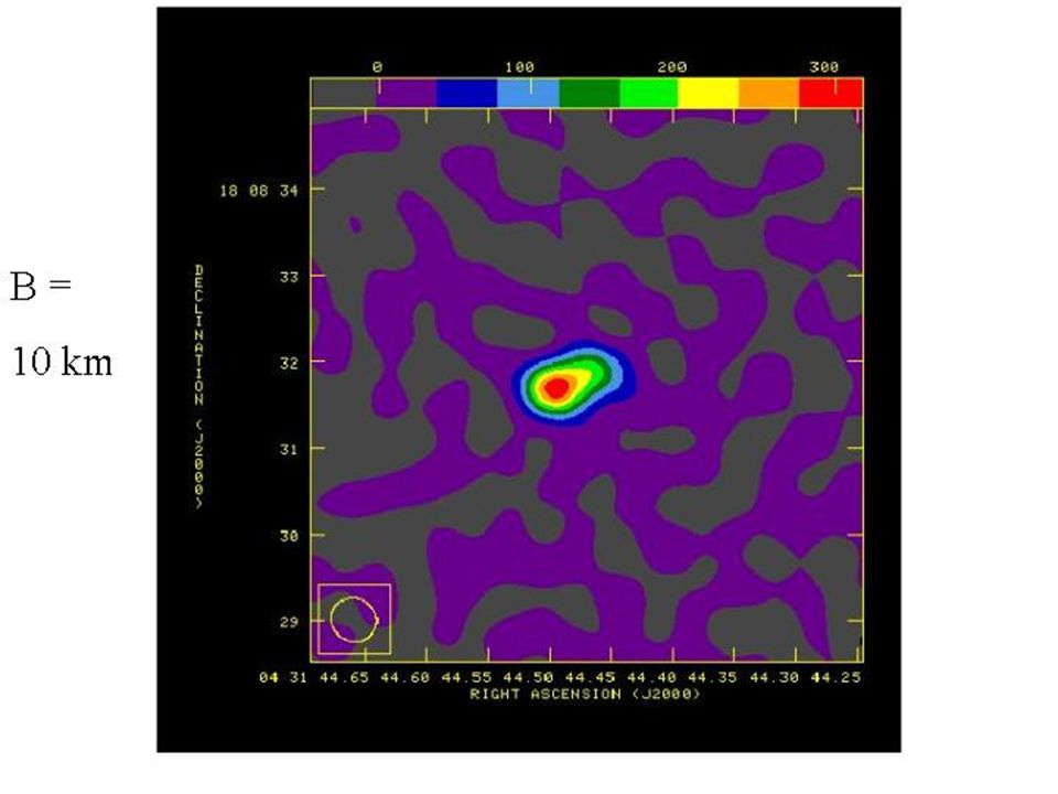
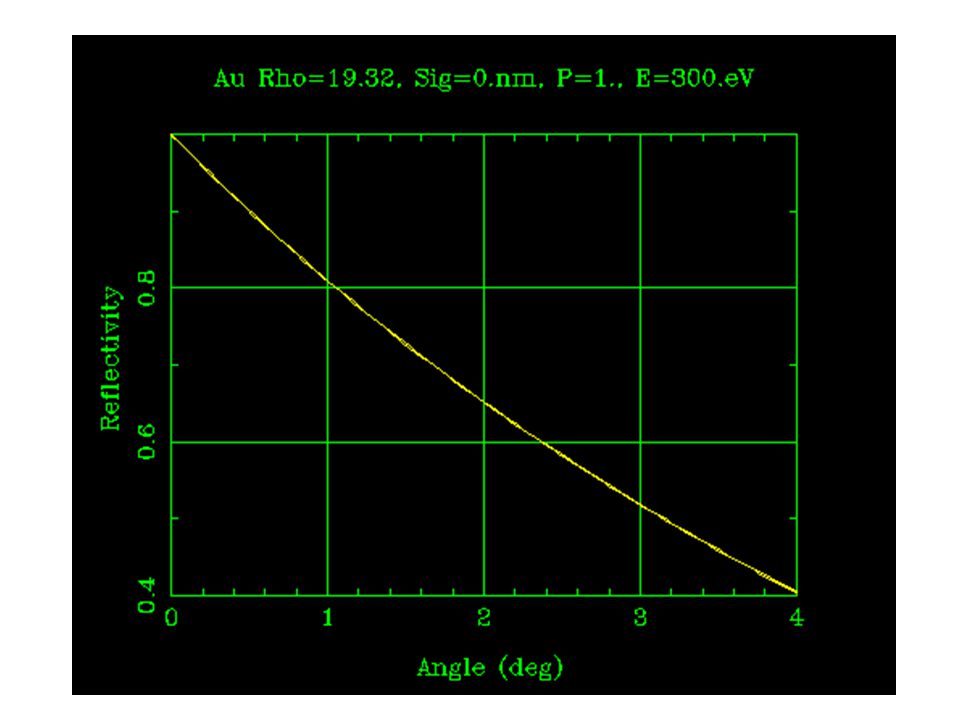
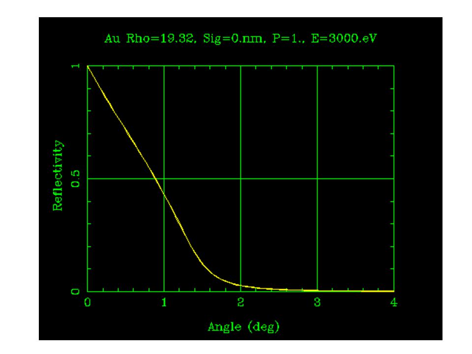
Uno de los tres telescopios del observatorio XMM-Newton.
58 espejos rasantes anidados. Angulo de incidencia = 0.5 grados. Cubiertos de oro

53
Para los rayos g el efecto es tan limitante que ya ni los espejos de incidencia rasante sirven y hay que recurrir a otras técnicas para hacer telescopios.

57
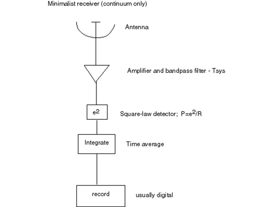
DETECTORES Radio (como ondas) IR (bolómetros)
Óptico y mas altas frecuencias (como partícula).
.")
59
Bolometer – diagram of 1 ‘pixel’
radiation thermistor wires absorber weak thermal link cold bath at fixed temperature Radiation is intercepted, absorber heats, and temperature change is measured by thermistor.
![]()
60
Actual bolometers

61
A closer look…

62
An even closer look… absorber: 1 mm square
doped silicon thermistor (invisible) leg = thermal link, wire on top
 leg = thermal link, wire on top.")
63
1 The CCD detector; 1.2 History
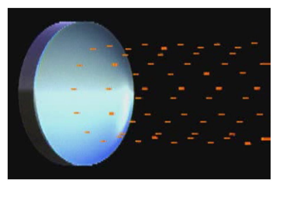
Additionaly to this essential characteristic, it appeared very quickly that this new circuit, build on a silicate based semi-conductor substrat, is very sensible to visible light. This has produced a revolution in the technology of light detectors, especially for astronomicaly oriented applications. But today, CCDs are also present in all instruments which use electronic imaging (cf. televisions, video systems, cameras, etc...). Astronomers have been among the first scientists who recognised the very extraordinary and very promising capabilities and performances of CCDs. Already in 1972, scientists at the Jet Propulsion Laboratory (JPL) in Pasadena (CA) have established a developpement program of CCDs for the purpose of space astronomy. Three years later, a team from JPL in collaboration with astronomers from the university of Arizona, have obtainded what is most probably the first astronomical image with a CCD camera (see the image in the previous page). Nowadays, all modern telescopes are equiped with instruments whose detectors are CCDs. Mainly, CCD detectors are present in visible light cameras for direct imaging … but also they serve as detectors for spectrographs. Additionnaly, most of the recent and future space missions (cf. Galileo, Hubble telescope, AXAF, etc.) are/will be equiped with instruments whose detectors are CCDs. They way a CCD works is very easy in principle. A very nice analogy, suggested by Jerome Kristian, is often used (see above figure): One can imagine a network of large buckets distributed in a regular manner on a large surface farm. After a strong downpour, the buckets filled with water are transported on conveyor belts to a weighting station where the quantity of water which poured on the farm‘s ground can be measured with high accuracy. Determining the brillance distribution of an astronomical object (star, planet, galaxie, a martian spacecraft ?) with the help of a CCD is pretty much similar to the measurments of the quantity of infalling rain on a farm. As soon as the rain stops, collecting buckets are displaced horizontally on conveyor belts. Then the water content of the buckets is collected in other buckets on a vertical conveyor belt. The overall content is sent onto a weighting system.
. Astronomers have been among the first scientists who recognised the very extraordinary and very promising capabilities and performances of CCDs. Already in 1972, scientists at the Jet Propulsion Laboratory (JPL) in Pasadena (CA) have established a developpement program of CCDs for the purpose of space astronomy. Three years later, a team from JPL in collaboration with astronomers from the university of Arizona, have obtainded what is most probably the first astronomical image with a CCD camera (see the image in the previous page). Nowadays, all modern telescopes are equiped with instruments whose detectors are CCDs. Mainly, CCD detectors are present in visible light cameras for direct imaging … but also they serve as detectors for spectrographs. Additionnaly, most of the recent and future space missions (cf. Galileo, Hubble telescope, AXAF, etc.) are/will be equiped with instruments whose detectors are CCDs. They way a CCD works is very easy in principle. A very nice analogy, suggested by Jerome Kristian, is often used (see above figure): One can imagine a network of large buckets distributed in a regular manner on a large surface farm. After a strong downpour, the buckets filled with water are transported on conveyor belts to a weighting station where the quantity of water which poured on the farm‘s ground can be measured with high accuracy. Determining the brillance distribution of an astronomical object (star, planet, galaxie, a martian spacecraft ) with the help of a CCD is pretty much similar to the measurments of the quantity of infalling rain on a farm. As soon as the rain stops, collecting buckets are displaced horizontally on conveyor belts. Then the water content of the buckets is collected in other buckets on a vertical conveyor belt. The overall content is sent onto a weighting system.")
64
1 The CCD detector 1.3 How does a CCD work ? (a) (b) Output Pixel
register Pixel (a) (b) Electrodes To Output amplification Electrons 1 The CCD detector Not only it becomes possible to know the overall quantity of rain which fell on the farm but also to know it‘s spatial distribution. A CCD detector works with the same principles, where rain drops are replaced by photons, the buckets by pixels, etc. (see above and next figure). 1.3 How does a CCD work ? In order to produce an image, a CCD must accomplish four functions: 1) generate photoelectrons (cf. rain drops), 2) collect electrons (cf. the buckets), 3) transfer the collected charges (cf. the conveyor belts), 4) read the charges (cf. weighting device). The first function is based on the photoelectric effect. The light absorption in the silicate network of the CCD generates these photoelectrons, in proportion to the number of incident photons. The latter are immedialtly collected at some specific locations, the closest to where the photons fell on the chip. Those sites (cf. the buckets) are called pixels (cf. “picture elements”). Those pixels are defined by means of an electrode network which covers the CCDs surface. The electrodes form some potential wells, to prevent the collected charges of escaping. When collecting the charges is finished, their transfer (cf. displacement of buckets on the conveyor belt) is realized by changing in a synchronized manner the potentiels at the limit of each electrode in such a way that electrons can moove horizontally from one pixel to the other. At the end of each horizontal line of pixels sits a couting device (output register). The way a CCD works is illustrated by means of a simplified CCD made of 9 pixels, an output register and an amplifier. Each pixel is divided in 3 regions (electrodes who serve to create a potential well). (a) when an exposure is made, the central electrode of each pixel is maintained at a higher potentiel (yellow) than the others ( green) and the charges collecting process takes place. (b) At the end of the exposure, the electrodes potentials are changed and charges transfered from one electrode to the other.
![]()
65
1 The CCD detector 1.3 How does a CCD work ? (a) (b) Impurity (doping)
Which is a serie of electrodes which lies outside the photosensible zone of the CCD and disposed in a perpendicular way to it. This output register sends one by one the charge packages to an output amplifier where, at the end of this chain, charges are digitalized and stocked into a computer harddisk. The registered signal can be afterwards calibrated, analysed ..ect. We can restitute in the form of a numerical image the brillance distribution of the observed astronomical object. 1.4 Advantages of CCDs In order to understand why CCDs are so useful and powerful, it is worth enumerating the essential characteristic of this detector. These characteristics are: 1) A good spatial resolution which allows astronomers to see the details at the surface of the studied object. 2) A very good quantum efficiency, which enables the detection of very faint objects. We require that the fraction of detected photons to be very high. 3) A efficient reponse in a very large spectral window. The detector should be sensible to the radiation in a large wavelenght domain. 4) A very low noise. The noise should remain very small compared to the weak signal emitted by faint objects. 5) A large domain for the strenght of detected signals (dynamical domain). The ratio of the fluxes of the faintest detected objects to the fluxes of the brightest one, should be as large as possible. By changing in a synchronized way the potential of the electrodes, electrons are transfered from pixel to pixel. Charges on the right are guided to the output register (b) The horizontal transfer of charges is then stopped and charge packages at the output register are transfered vertically, one by one, to an output amplifier and then read one by one. The cycle starts again until all the charges have been read (reading time of about 1 minute for a large CCD).
 A good spatial resolution which allows astronomers to see the details at the surface of the studied object. 2) A very good quantum efficiency, which enables the detection of very faint objects. We require that the fraction of detected photons to be very high. 3) A efficient reponse in a very large spectral window. The detector should be sensible to the radiation in a large wavelenght domain. 4) A very low noise. The noise should remain very small compared to the weak signal emitted by faint objects. 5) A large domain for the strenght of detected signals (dynamical domain). The ratio of the fluxes of the faintest detected objects to the fluxes of the brightest one, should be as large as possible. By changing in a synchronized way the potential of the electrodes, electrons are. transfered from pixel to pixel. Charges on the right are guided to the output register. (b) The horizontal transfer of charges is then stopped and charge packages at the output. register are transfered vertically, one by one, to an output amplifier and then read one. by one. The cycle starts again until all the charges have been read (reading time of about. 1 minute for a large CCD).")
66
1 The CCD detector 1.4 Advantages of CCDs Mosaïc of 4 CCDs, containing
each 2040 x 2048 pixels. This composite detector is about 6 cm large and contains a total of 16 millions pixels (Kitt Peak National Observatory, Arizona). 1 The CCD detector Since it is not possible to build larger and larger CCD chips ( because of the costs), the remedy to this problem was to put side by side a number of smaller chips in a kind of a CCD mosaïc (cf. Above figure). The pixels size is of the order of 15 15 or 25 25 microns. As much as these numbers may look enormous, in fact the size of CCD chips remains quite small , especially when we compare CCDs to classical photographic plate images. A CCD which has 2048 2048 pixels, for which the pixel individual size is 15 microns, measures only 3 3 cm. A photographic plate for a Schmidt telecope could be as big as 30 30 cm, which means 100 times larger than the CCD, or equivalently to a CCD chip with 400 millions pixels ! .
. 1 The CCD detector. Since it is not possible to build larger and larger CCD chips ( because of the costs), the remedy to this problem was to put side by side a number of smaller chips in a kind of a CCD mosaïc (cf. Above figure). The pixels size is of the order of 15 15 or 25 25 microns. As much as these numbers may look enormous, in fact the size of CCD chips remains quite small , especially when we compare CCDs to classical photographic plate images. A CCD which has 2048 2048 pixels, for which the pixel individual size is 15 microns, measures only 3 3 cm. A photographic plate for a Schmidt telecope could be as big as 30 30 cm, which means 100 times larger than the CCD, or equivalently to a CCD chip with 400 millions pixels ! .")
67
1 The CCD detector 1.4 Advantages of CCDs
However, CCDs possess advantages which clearly distinguish them from photographic plates, and from all other detectors in general. 2) The above figure compares the quantum efficiency of a CCD with the one of other types of detectors. The eye- the first astronomical detector- possesses at visible wavelenght a quantum efficienty of around one percent. In other words, we can only detect one single photon among one hundred who hit our eye. In contrast, more than 50 ( 80 at certain wavlenghts) of photons falling on the surface of a CCD are detected. 3) Additionnaly, the domain of spectral response of our eye is much more narrower compared to the one of the CCD. This limiation affects also other detectors as photocatods, photographic plates, ... It is noticable that when a CCD is illuminated from above, it is rather insensitive to ultraviolet light and X rays, the electrodes surrounding each individal pixel beeing opaque to these types of photons. We can improve by about 20 the quantum efficiency of CCDs in the ultraviolet by covering the upper surface by a thin layer of phosphore which main task is to convert ultrviolet photons to photons who have a higher wavelenght. A much more performant method consists in making the CCD very thin and illuminating it from the bottom. The incident photons can then enter in contact with the photosensible area of the CCD, without beeing absorbed by electrodes. However, at this face of the CCD (bottom) appears a potential well who tends to trap the photoelectrons at the bottom surface. Ingeneers have found two solutions to deal with this problem. The first method ( called “back side charging”) consists in flashing the CCD by means of an ultraviolet light before using it. In this way, an excess of photoelectrons is produced which destroys the potential well at the bottom surface of the CCD. Quantum efficiency curves of different types of CCDs as a function of the wavelenght compared to the one of other detectors. We can see on this plot the large domain of wavelenghts for the spectral response of CCDs.
 The above figure compares the quantum efficiency of a CCD with the one of other types of detectors. The eye- the first astronomical detector- possesses at visible wavelenght a quantum efficienty of around one percent. In other words, we can only detect one single photon among one hundred who hit our eye. In contrast, more than 50 ( 80 at certain wavlenghts) of photons falling on the surface of a CCD are detected. 3) Additionnaly, the domain of spectral response of our eye is much more narrower compared to the one of the CCD. This limiation affects also other detectors as photocatods, photographic plates, ... It is noticable that when a CCD is illuminated from above, it is rather insensitive to ultraviolet light and X rays, the electrodes surrounding each individal pixel beeing opaque to these types of photons. We can improve by about 20 the quantum efficiency of CCDs in the ultraviolet by covering the upper surface by a thin layer of phosphore which main task is to convert ultrviolet photons to photons who have a higher wavelenght. A much more performant method consists in making the CCD very thin and illuminating it from the bottom. The incident photons can then enter in contact with the photosensible area of the CCD, without beeing absorbed by electrodes. However, at this face of the CCD (bottom) appears a potential well who tends to trap the photoelectrons at the bottom surface. Ingeneers have found two solutions to deal with this problem. The first method ( called back side charging ) consists in flashing the CCD by means of an ultraviolet light before using it. In this way, an excess of photoelectrons is produced which destroys the potential well at the bottom surface of the CCD. Quantum efficiency curves of different types of CCDs as a function of the wavelenght. compared to the one of other detectors. We can see on this plot the large domain of. wavelenghts for the spectral response of CCDs.")
68
Los fotones de rayos X ionizan el gas que hay en el tubo y los electrones libres producto de la ionización crean una corriente que se puede medir. Como gas se emplea argón y otros gases nobles como kriptón o xenón porque no interfieren con los electrones liberados.

70
Debido a que los distintos tipos de fotones o de partículas tienen distinta penetrabilidad, es posible blindar el “receptor” para que solo detecte de un tipo.

Presentaciones similares